Plate Elements: Local Axes
Local x, y axes
3-Node and 4-Node elements
The default local axis system for these elements is shown below and is constructed from the nodes N1, N2, N3 for the triangle and N1, N2, N3, N4 for the quadrilateral element as follows:
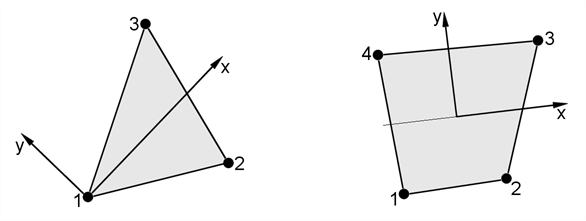
- Positive local x joins the mid-sides from side (N1,N4) to side (N2,N3) for the quadrilateral element, or goes from N1 to bisect side (N2,N3) for the triangle.
- Positive local y is normal to the local x axis directed away from side (N1,N2) and lies in the plane of the plate.
6-Node, 8-Node and 9-Node elements
The 8-Node and 9-Node elements have four curved sides with nodes N1 to N4 at the corners and nodes N5 to N8 on the sides but not necessarily at the geometric mid points. Each side is a quadratic curve in XYZ-space (like a parabola) defined by the three points on that side. The mid-side nodes normally lie in the range 0.25 to 0.75 of the side; outside this range the element performance may degrade. The nodes N1 to N8 (N9), define a set of curvilinear coordinates.
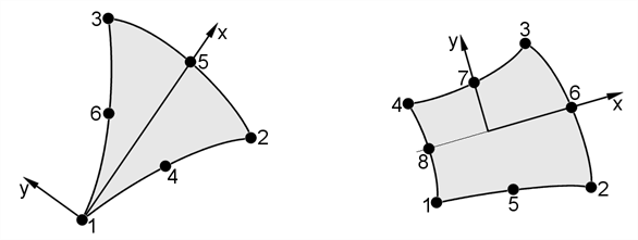
The spatial transformations involved in this 8-Node isoparametric element are such that each side of the element can only be a quadratic curve in Cartesian XYZ space. This should be considered when modelling structures of complex shape.
The local coordinate system for the 6-Node triangle is also shown above. This coordinate system is obtained from that for the 8-Node element if the triangle is formed by collapsing nodes N1 and N4 onto N8.
In Strand7, the local x and y axes of any plate element may be reorientated in the plane of the element by rotating them about the normal to the z axis. This is useful for orientating the local x axis (say) for a range of elements such that the axis follows a specific direction, or to enable a consistent layup of laminated composite materials or orthotropic materials. The local z axis is defined by the node numbering order.
Local z axis
In all plate elements the positive local z axis is normal to the plate surface completing a right hand system with the local x and y axes.
The local z axis is important in that it defines the surface of a plate element. In Strand7 we refer to either the -z or the +z surface of a plate element, with reference to the direction of the local z axis. The surface of a plate element is used to the application of surface specific attributes like normal pressure, and for the extraction of stresses that can vary through the thickness.
Local u, v axes
A parametric coordinate system is also defined on the plate elements using the local (u, v) coordinates. The u and v coordinate range is always defined to be between -1 and +1 for quadrilaterals and between 0 and +1 (with some restrictions) for triangles.
Note that while the (x, y) axes are Cartesian axes, the (u, v) axes are parametric axes and therefore may not be orthogonal in 3D space.
Triangular Plate Faces
The figure below shows the u-v coordinates for triangular plates.
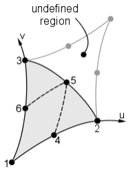
| Node | Coordinates | |
| u | v | |
| 1 | 0 | 0 |
| 2 | 1 | 0 |
| 3 | 0 | 1 |
| 4 | 0.5 | 0 |
| 5 | 0.5 | 0.5 |
| 6 | 0 | 0.5 |
Quadrilateral Plate Faces
The figure below shows the u-v coordinates for quadrilateral plates.
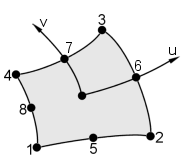
| Node | Coordinates | |
| u | v | |
| 1 | -1 | -1 |
| 2 | 1 | -1 |
| 3 | 1 | 1 |
| 4 | -1 | 1 |
| 5 | 0 | -1 |
| 6 | 1 | 0 |
| 7 | 0 | 0 |
| 8 | -1 | 0 |
See Also