Plate Elements: Stiffness Factors
Description
Individual components of the local stiffness matrix for linear isotropic plate elements can be scaled by assigning stiffness factors. Stiffness scaling is usually applied to introduce a localised flexibility in a particular direction of a mesh, while keeping the stiffness in the other directions unchanged.
The Plate Attributes: Stiffness/Mass Factor attribute is applicable to the plate/shell, 2D plane stress, 2D plane strain, axisymmetric and shear panel plate element types. It provides the option to independently scale each of the following components of the plate stiffness matrix:
-
Cxx
Membrane stiffness in the local x direction - applies to all plate types except shear panel.
-
Cyy
Membrane stiffness in the local y direction - applies to all plate types except shear panel.
-
Cgg
Membrane stiffness in-plane shear - applies to all plate types.
-
Czz
Normal stiffness - applies to plane strain and axisymmetric plates.
-
Dxx
Bending stiffness in the local x direction - applies to shell types.
-
Dyy
Bending stiffness in the local y direction - applies to shell types.
-
Dgg
Bending stiffness in the local twist direction - applies to shell types.
-
Gxz
Transverse shear stiffness normal to the local x direction - applies to thick shell types.
-
Gyz
Transverse shear stiffness normal to the local y direction - applies to thick shell types.
The attribute is applicable only to isotropic materials. The scaling operation is implemented by effectively converting the element to an equivalent orthotropic material whenever any scaling factors are not 1.0.
For an isotropic material, Strand7 requires the definition of  and
and  . To convert this to an orthotropic material we set
  and
and  . From these material parameters the element stiffness matrix is assembled.
To ensure that the stiffness matrix remains symmetric, the following relationships must hold in an orthotropic material:


From these relationships we can see that if  then
then  . Therefore, if we scale
  by the Cxx factor defined in the attribute, we will also need to scale the Poisson's ratios to keep the orthotropic relationships valid. If we assume that the isotropic value of Poisson's ratio defined for the material is
  , we could calculate
  . However, if
  is zero because Cxx has been set to zero, which is allowed, we cannot calculate
  .
.
To overcome this limitation, Strand7 sets either  or
or  based on the magnitude of the respective scaling factors applied in the attribute. In this way, the other Poisson's ratios can always be calculated.
For example, considering just the in-plane stiffness of a plate element:
- If we have defined the scaling factors for the attribute as Cxx=0.25 and Cyy=1.0, the orthotropic element stiffness matrix will use the following material coefficients:


- If we have defined the scaling factors for the attribute as Cxx=1.0 and Cyy=0.25, the orthotropic element stiffness matrix will use the following material coefficients:


Example
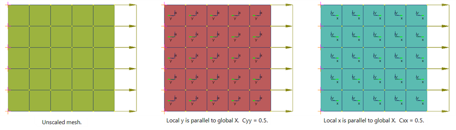
An isotropic plate mesh with Poisson's ratio of 0.3 is modelled. The mesh is fully restrained at one end, and loaded with a uniform tensile stress at the other end. Three meshes are compared:
- An unscaled mesh.
- A mesh with Cyy = 0.5, where the local y direction of the plates is parallel to the global X direction.
- A mesh with Cxx = 0.5, where the local x direction of the plates is parallel to the global X direction.
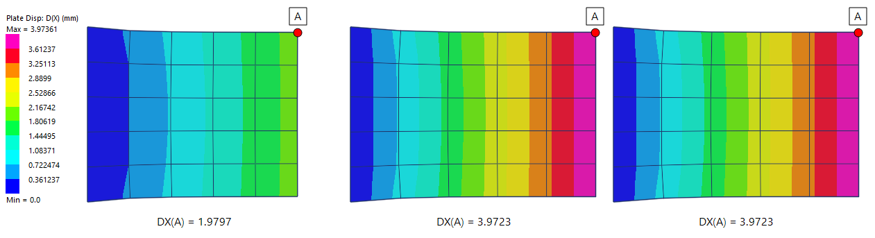
Meshes 2 and 3 are expected to produce the same results.
The following image compares the global X displacements.
The following image compares the global Y displacements.
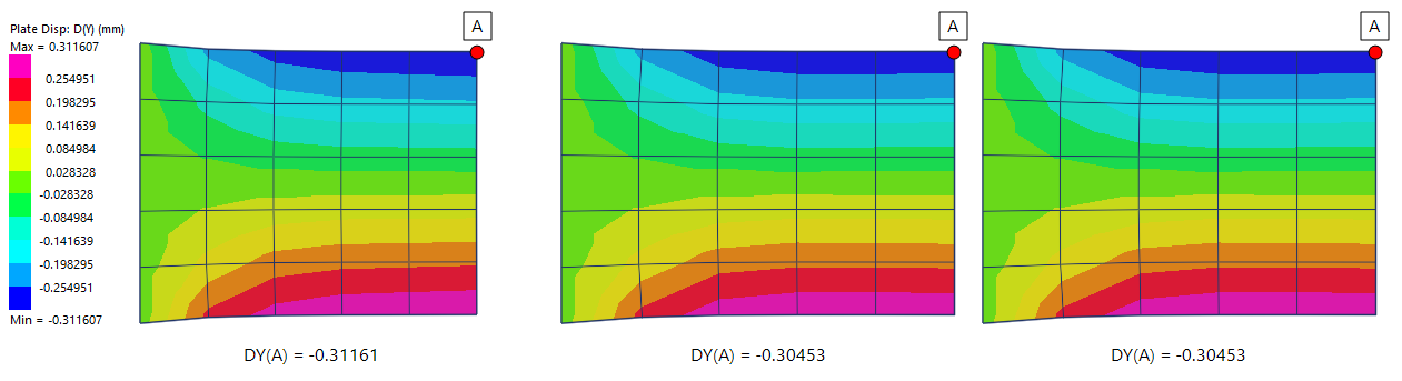
The two scaled meshes produce the same displacements, even though different directions have been scaled.
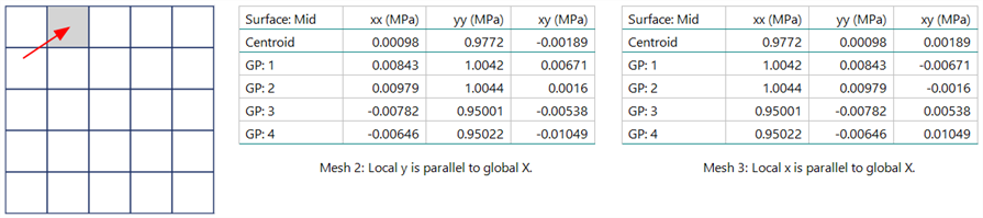
The local stresses at the Gauss points for the plate indicated also match for the two scaled meshes.
See Also