Brick Cutting Planes: Planes Tab
Description
Defines and lists cutting planes. Cutting planes allow for results to be visualised inside brick elements.
Cutting planes are defined parallel to a UCS plane at an origin point defined by coordinates expressed in the same UCS.
Dialog
Insert plane
Inserts a new cutting plane before the currently selected row in the table.
Add plane
Adds a new cutting plane at the end of the table.
Delete selected planes
Deletes the selected cutting planes.
Lock/unlock plane position - Axis (1,2,3)
If set, unlocks the Axis columns in the table for editing, allowing the origin of each cutting plane to be changed.
If not set, the Axis columns remain locked.
Show/hide brick outlines
If set, draws outlines of the brick mesh around the cutting plane.
Brick outline display can be adjusted from entity display options.
Show/hide plane axes
If set, visual axes are drawn at the origin of the cutting plane.
Selections
Sets all, clears all or inverts the status of the Show column for each cutting plane.
Update display
Updates the display of cutting planes.
Cutting planes do not update automatically after changes to their definition. The update display icon must be clicked when an update is required.
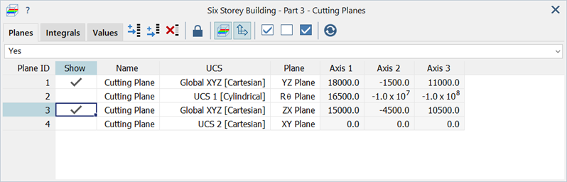
Planes Table
Table with each row corresponding to a cutting plane.
-
Plane ID
Number of the cutting plane.
-
Show
If set, the cutting plane is displayed.
Cutting planes are only shown if a brick result quantity is active.
-
Name
Identifier name for the cutting plane.
-
UCS
Coordinate system in which the cutting plane is defined.
-
Plane
Plane used to orientate the cutting plane.
The cutting plane is parallel to one of the principal planes of the selected coordinate system (UCS).
-
Axis 1 / 2 / 3
The coordinates of the cutting plane origin point in the selected coordinate system (UCS).
Coordinates of a point can be retrieved by clicking the point in the model when the plane is unlocked.
See Also