Mesh Tools: Cut Elements
Description
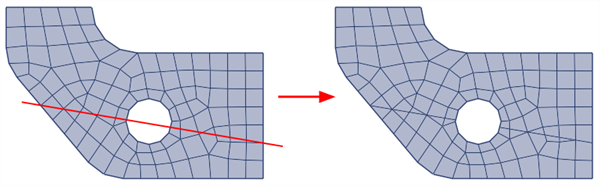
Cuts selected elements using a straight line, a plane, or a cylindrical surface.
Beams can be created at cut plate edges, and plates can be created at cut brick faces.
Dialog
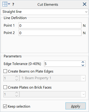
Straight Line Cut
Cuts selected beam and plate elements along their intersection with a straight line.
The line is defined by Point 1 and Point 2.
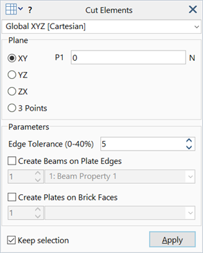
Planar Cut (Cartesian UCS)
Cuts selected beam, plate and brick elements using the selected plane.
Two options are available to define the plane:
-
XY / YZ / ZX
Cutting plane passes through point P1 and is parallel to a principal plane of the selected UCS.
If P1=0 the plane passes through the origin of the selected UCS.
-
3 Points
Cutting plane passes through three points P1, P2 and P3. All three must be non-zero.
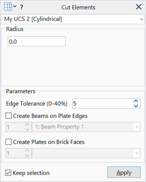
Cylindrical Cut (Cylindrical UCS)
Cuts selected beam, plate and brick elements using a cylindrical surface.
The cylinder is aligned with the UCS and has a constant radius as specified by Radius.
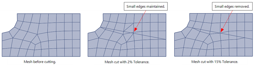
Edge Tolerance
Specifies the minimum beam or edge length allowed as a result of the cut, expressed as a percentage of the edge length prior to the cut.
If a cut results in new beams or edges that are shorter than this length, the short beams and edges are collapsed to their respective intersection points.
Create beams on plate edges
If set, beams are created on cut plate edges.
Beams generated by the tool are assigned the specified beam property. See Beam Attributes: Property Type.
Create plates on brick faces
If set, plates are created on cut brick faces.
Plates generated by the tool are assigned the specified plate property. See Plate Attributes: Property Type.
Common Controls
Validity of cut elements
When cutting a triangle, the cut can produce:
- two triangles, or
- a triangle and a quadrilateral.
Both of these are valid plate and brick shapes and they will generate the appropriate element types after cutting.
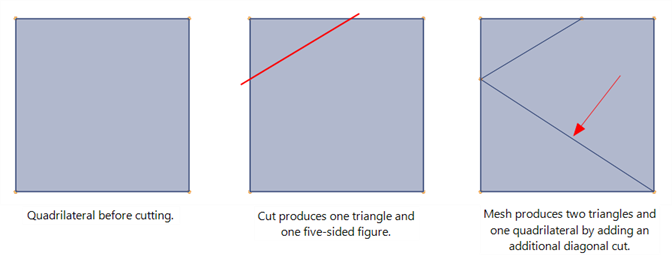
When cutting a quadrilateral, the cut can produce:
- two quadrilaterals, or
- two triangles, or
- a triangle and a quadrilateral, or
- a five-sided shape.
The five-sided shape is not a valid element shape, and therefore it is subdivided further into a quadrilateral and a triangle.
See Also