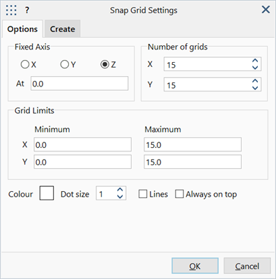
Snap Grid Settings: Options Tab
Description
Defines the display, position, spacing and number of snap grid points.
Snap grid is defined in terms of the currently active coordinate system.
Dialog
Fixed Axis - (X / Y / Z)
Fixed coordinate in the currently active coordinate system. The remaining two axes define the working surface or plane on which the snap grid lies.
Fixed Axis - At
Ordinate value of the fixed axis.
For example, in the Cartesian coordinate system, an XY plane could be defined by fixing the Z axis at Z=5. This would form a grid plane parallel to both the X and Y axes passing through the Z axis at Z=5. In a cylindrical coordinate system, a surface can be defined by fixing the R axis. This would then form a cylindrical grid surface with a constant radius.
Number of grids (X / Y)
Number of divisions within the snap grid limits.
Grid Limits
Limiting coordinates of the free axes, defining the extent and size of the snap grid.
Units are either degrees (if angular) or the length unit of the model (if linear), depending on the active coordinate system type.
Colour
Colour of the grid points.
Click the colour square to open a Colour Selection dialog to change the colour. Note that the colour is automatically adjusted when selecting colours that are the same as the model window background colour - for example, selecting white grid points on a which background will produce black grid points instead.
Dot Size
Pixel size of the grid points.
Lines
If set, lines are drawn between the grid points.
If not set, only grid points are drawn.
Always on top
If set, snap grid points and lines are drawn in front of all other entities.
If not set, snap grid points and lines are drawn at in true model space and therefore may be obscured by other entities, depending on the view angle.
See Also