Results Interpretation: Beam Force and Moment Conventions
Description
Beam force and moment results are available at the ends of a beam and anywhere along its length.
Beam forces and moments can be extracted in Results Peek: Entity Tabs via the End Force quantity with reference to the beam local axis system, the beam principal axis system, the global Cartesian system and any UCS.
The diagram options in Results Peek: Entity Tabs provide a graphical 2D representation of the forces and moments in the Plane 1, Plane 2, Plane x, Plane y and Axial reference systems.
Beam forces and moments can be listed in The LISTINGS Tab with reference to the beam local axis system, the beam principal axis system, the global Cartesian system and any UCS.
For these result quantities, Straus7 uses the following conventions.
Axial Force
The sign of the axial force denotes whether the beam is in tension (positive sign) or in compression (negative sign). This convention applies when looking at the results at either end of the beam, or at any position along it.
Shear Force and Bending Moment
These results are provided in two sets of orthogonal planes.
- The Principal Planes
These are denoted as Plane 1 (the plane on which the principal 1 axis lies) and Plane 2 (the plane on which the principal 2 axis lies). - The Local Planes
These are denoted as Plane x (the plane on which the local x axis lies) and Plane y (the plane on which the local y axis lies).
On each plane there is one shear force and one bending moment. For example, on Plane 1 there is Shear 1 and Moment 1. Here Moment 1 is not the moment about the 1 axis, but the moment on Plane 1. Similarly there are (Shear 2, Moment 2), (Shear x, Moment x) and (Shear y, Moment y).
In each plane, there is a consistent convention regarding the signs of these forces and moments.
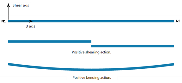
If we consider a point anywhere along the beam, a positive shear force shears the end 1 side of the point towards the positive direction of the axis.
A positive bending moment anywhere along the beam deforms the beam concave upward towards the positive side of the axis.
These are illustrated in the image below.
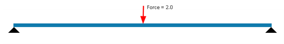
Consider a simply-supported beam with a shear force applied in the middle.
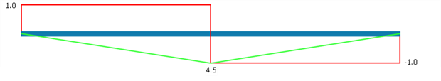
The classical display of the shear force (red) and bending moment (green) diagrams is as follows.
From a finite element modelling point of view, there are four permutations of orientations of the shear axis direction and the 3 axis direction for this simply-supported beam: the 3 axis can be directed from left to right or from right to left; the shear axis can point upward or downward.
Depending on the orientation of the element, the shear force at the left side of the beam can be reported as either positive or negative, according to the convention illustrated above. Furthermore, because the shear force diagram in Straus7 is drawn with respect to the axes of the beam, the shear force diagram can be either above or below the beam, depending on the axis direction.
Similarly, the sign of the bending moment can also change between the different orientations to ensure that the above convention for positive moment remains consistent. When displaying beams graphically, the bending moment diagram in Straus7 can be drawn either on the side of the beam that produces tensile bending stress or on the side that produces compressive bending stress, depending on the option selected.
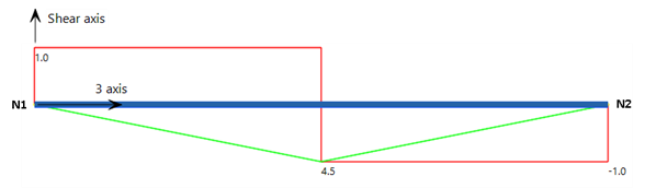
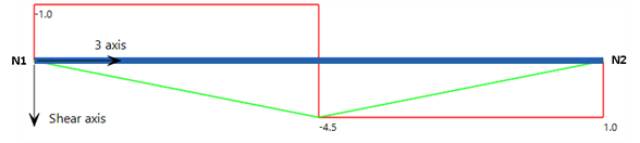
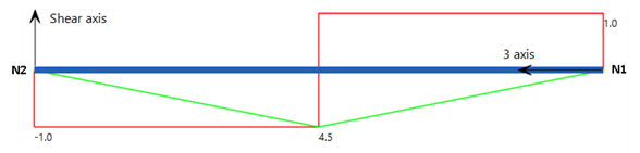
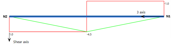
The following are the four permutations of shear axis and 3 axis directions, together with their corresponding shear force and bending moment diagrams and values. In each case, the same physical beam and load are being modelled, but the beam element is defined differently. In each case the bending moment is drawn on the tension side.
Case 1: Node 1 is at the left end, and the shear axis is positive upward: shear force at left end is reported as positive; bending moment is reported as positive.
Case 2: Node 1 is at the left end, and the shear axis is positive downward: shear force at left end is reported as negative; bending moment is reported as negative.
Case 3: Node 1 is at the right end, and the shear axis is positive upward: shear force at left end is reported as negative; bending moment is reported as positive.
Case 4: Node 1 is at the right end, and the shear axis is positive downward: shear force at left end is reported as positive; bending moment is reported as negative.
Torque
Torque follows the right-hand rule such that positive torque generates a positive twist about the axial direction of the beam (i.e., about the principal 3 axis, or local z axis).
Force and Moment Conventions in Global Axes
When extracting beam forces and moments at an intermediate position (i.e., a cut) along a beam element, the signs of the forces and moments reported by Straus7 are taken from the equilibrating forces on the End 2 side of the cut. This is illustrated for the simple case of an axial force via the following examples.
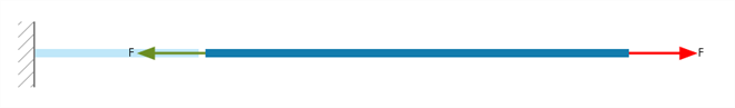
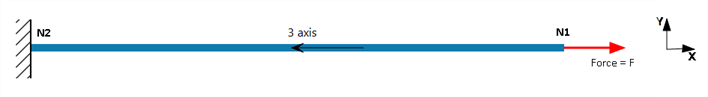
Case 1: Consider the beam shown below. It is parallel to the global X axis, fixed at the left end and pulled in tension via a force at the right end. Node 1 is at the left end and Node 2 is at the right end. Therefore the principal 3 axis points from left to right. The principal axial force (i.e., F3) will be positive (the beam is in tension).
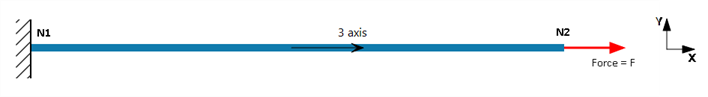
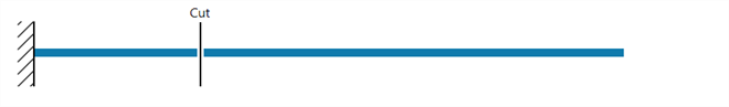
The global forces at any point along the beam can be considered by cutting the beam as follows and plotting the free body diagram:

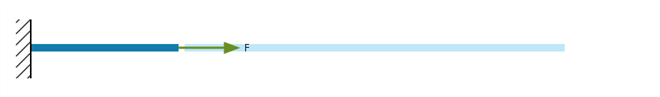
Now we look at the part of the beam towards Node 2. The forces produce the following free body diagram:
So FX (global force) at the cut will be negative (green arrow points in the negative X direction).
Case 2: Consider the beam shown below. It is physically the same at the one above except that Node 1 is at the right end and Node 2 is on the left end. The principal axial force (i.e., F3) will still be positive (tensile).
We make the cut at the same physical position as in Case 1:
Again we look at the part of the beam towards Node 2, but this is now on the left side. The forces produce the following free body diagram:
So FX (global force) at the cut on this beam will now be positive (green arrow points in the positive X direction).
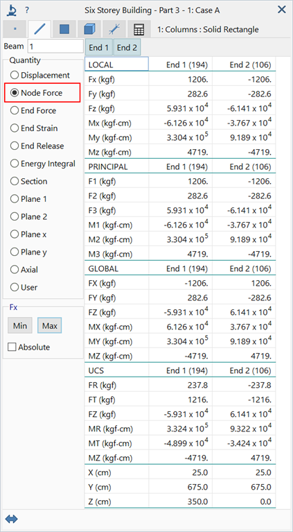
Node Force
Both Results Peek: Entity Tabs and The LISTINGS Tab provide a force/moment vector at the nodes of the beam. This is called the Node Force result; it comprises six values at each node (three forces and three moments) that represent the free body diagram of the beam at the nodes. The Node Force result is not specific to beam elements; it is available for all element types.
For beam elements, the Node Force results may be reported in the global axis system, which is the system in which the solver calculates them, as well as in a UCS and in the Local and Principal axis systems of the beam.
The signs of the Node Force results may not be the same as those of the End Force results. Node Force results do not use the conventions described above, irrespective of the axis system in which they are reported; for Node Force, the global results are simply transformed to the requested axis system as any vector would be transformed.
The values of the Node Force results can also be different to those of the End Force results because the ends of a beam may not be located at its nodes; examples include end-released and offset beams.
See Also