File Formats: Beam Section Library
Description
Beam cross sections based on the standard cross section shapes can be stored in, and retrieved from, a .BSL file using Properties: Import/Export Beam Sections. To create a new beam section library consisting of a large number of beam section data sets, the Utility: Make Library function can be used. To use this function to create a new beam standard cross section library, a source text file in the format described below is required.
The source text file must be encoded in UTF-8. Floating point data can be entered in either fixed format (e.g., 23.454) or exponential format (e.g., 2.3454E1). The exponent character can be either 'e' or 'E'. The decimal separator can be either a period (.) or a comma (,). Either character can be used as the decimal separator without having to specify it, as long as the file contains one or the other, not both. Both period and comma are allowed in the section and material name fields. Comment lines are allowed and are prefixed by a "/". Data fields are separated by space or tab characters.
There are 32 beam cross section library fields, 10 of which are material-related. The fields are arranged in the following order:
- Section name: must be between one and 250 characters long; must be enclosed in double quotes (e.g., "125 × 75 × 6 UA").
- Section type: must be one of the following strings (no spaces) - SolidRound, HollowRound, SolidRect, HollowRect, LipChannel, TopHat, Angle, IBeam, TBeam, ZBeam, SolidTrapezoid, HollowTrapezoid, SolidTriangle, HollowTriangle or Cross.
- Section dimension 1 (see the Section Types table below).
- Section dimension 2 (see the Section Types table below).
- Section dimension 3 (see the Section Types table below).
- Section dimension 4 (see the Section Types table below).
- Section dimension 5 (see the Section Types table below).
-
Section dimension 6 (see the Section Types table below).
- Cross section area.
- Second moment of area about the principal 1 axis, I11. Note that I11 is not necessarily greater than I22 as the principal 1 axis is always parallel to the local x-axis for singly and doubly symmetrical sections.
- Second moment of area about the principal 2 axis, I22.
- Torsion constant J.
- Shear centre position in the principal 1 axis relative to the centroid of the cross section.
- Shear centre position in the principal 2 axis relative to the centroid of the cross section.
- Shear area in the principal 1 axis.
- Shear area in the principal 2 axis.
- Material Name: must be between one and 250 characters long; must be enclosed in double quotes (e.g., "Structural Steel").
- Elastic modulus.
- Shear modulus.
- Poisson's ratio.
- Mass density.
- Thermal expansion coefficient.
- Thermal conductivity.
- Specific heat.
- Viscous damping coefficient.
-
Mirror type: an integer from 0 to 12, defining the way a composite section may be constructed (see the Mirror Types table below).
- Gap A: the "A" distance between mirrored sections (see the Mirror Types table below).
- Gap B: the "B" distance between mirrored sections (see the Mirror Types table below).
- Cx: centroid position in the local x axis from the minimum x-y coordinate of the beam section.
- Cy: centroid position in the local y axis from the minimum x-y coordinate of the beam section.
- Principal axis angle: the angle between the principal 1 axis and the local x axis, in degrees. For singly and doubly symmetrical sections, including mirrored sections, such as columns, channels, Mirror Left, etc., the principal axis angle is set to zero if it is not specified. Other sections and mirror types such as angles, zeds, Mirror Left Top Only, etc., Strand7 calculates the principal axis angle if it is not specified.
- Use shear modulus. If this field contains the text "Shear", the material uses Shear Modulus under the Materials tab instead of Poisson's Ratio (ν).
Any data omitted after the last value of each data set is treated as null (i.e., zero value).
An example of beam cross section library source file with four cross sections is shown below.
Sample
/My custom beam simplified sections
/Units: SI
/Designation Type D1 D2 D3 T1 T2 T3 Area I11 I22 J SC1 SC2 SA1 SA2 Material E G nu rho alpha lambda Cp c Mirror GapA GapB CX CY Angle
"Custom - 310 UC 158" IBeam 0.3272 0.311 0.311 0.025 0.025 0.0157 0.02014 3.88E-4 1.25E-4 3.81E-6 0 0 1.348E-2 4.741E-3 "AS4100 Steel" 2E+11 8E10 0.25 7850 1.17E-05 50 4.8E+02
"Custom - T 50 × 100 × 6 × 8 (TW)" TBeam 5.0E-2 1.0E-1 0 8.0E-3 6.0E-3 0 1.079E-3 1.61E-7 6.68E-7 2.353341E-8 0 5.303928E-3 7.179160E-4 2.494608E-4 "GB50017 Steel" 2.06E+11 7.9E+10 3.0E-1 7.85E+03 1.2E-5 5.0E+1 4.8E+2 0 0 0 0 5.0E-2 4.0E-2
"Custom - 2L 4 × 3-1/2 × 1/4 × 3/8 SLBB" Angle 8.89E-02 1.02E-01 6.35E-03 6.35E-03 0.00E+00 0.00E+00 2.35E-03 1.72E-06 5.08E-06 0.00E+00 0.00E+00 0.00E+00 0.00E+00 0.00E+00 "ANSI/AISC 360:2016 Steel" 2.00E+11 7.72E+10 3.00E-01 7.86E+03 1.17E-05 5.10E+01 5.00E+02 0.00E+00 3.00E+00 9.00E-03 0.00E+00 1.065E-01 2.28E-02
"Custom - 90 × 45 mm Timber Framing" SolidRect 9.00E-2 3.50E-2 0 0 0 0 3.15E-3 2.12625E-6 3.21563E-7 9.71188E-7 0 0 0 0 "Timber - MGP10 (Average Modulus) - AS 1720-1-2010" 1.000E10 6.70E8 0 500 0.0000035 0.00E+00 0.00E+00 0.00E+00 "Shear"
"Custom - Cold Formed Angles (Unequal Leg) 50 x 25 x 2.0" Angle 5.000000E-02 2.500000E-02 2.000000E-03 2.000000E-03 0.000000E+00 0.000000E+00 1.430000E-04 4.075471E-08 4.114571E-09 1.867801E-10 -8.380105E-03 -1.461899E-02 3.559388E-05 8.092640E-05 "Structural Steel" 2.000000E+11 7.700000E+10 3.000000E-01 7.850000E+03 1.170000E-05 5.000000E+01 4.800000E+02 0.000000E+00 0.000000E+00 0.000000E+00 0.000000E+00 5.050000E-03 1.790000E-02 2.798391E-01
Section Types
All six section dimensions must be specified for each data set. Not all section types use all six values. Unused dimensions should be set to 0.
| Cross section type | Section dimensions | Illustration | |||||
|
|
1 |
2 |
3 |
4 |
5 |
6 |
|
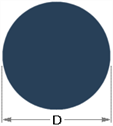
| SolidRound | D | zero | zero | zero | zero | zero |
|
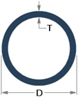
| HollowRound | D | T | zero | zero | zero | zero |
|
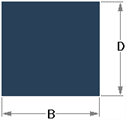
| SolidRect | D | B | zero | zero | zero | zero |
|
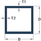
| HollowRect | D | B | T1 | T2 | zero | zero |
|
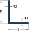
| Angle | D | B | T1 | T2 | zero | zero |
|
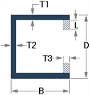
| LipChannel | D | B | L | T1 | T2 | T3 |
|
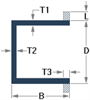
| TopHat | D | B | L | T1 | T2 | T3 |
|
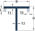
| TBeam | D | B | L | T1 | T2 | T3 |
|
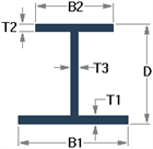
| IBeam | D | B1 | B2 | T1 | T2 | T3 |
|
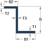
| ZBeam | D | B1 | B2 | T1 | T2 | T3 |
|
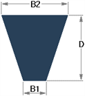
| SolidTrapezoid | D | B1 | B2 | zero | zero | zero |
|
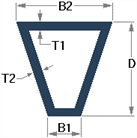
| HollowTrapezoid | D | B1 | B2 | T1 | T2 | zero |
|
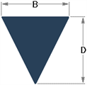
| SolidTriangle | D | B | zero | zero | zero | zero |
|
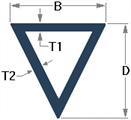
| HollowTriangle | D | B | T1 | T2 | zero | zero |
|
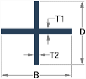
| Cross | D | B | T1 | T2 | zero | zero |
|
MirrorTypes
| Mirror type | Description | Illustration |
| 0 | Not mirrored (standard single section) |

|
| 1 | Mirror Top |

|
| 2 | Mirror Bottom |

|
| 3 | Mirror Left |

|
| 4 | Mirror Right |

|
| 5 | Mirror Left And Top |

|
| 6 | Mirror Left And Bottom |

|
| 7 | Mirror Right And Top |

|
| 8 | Mirror Right And Bottom |

|
| 9 | Mirror Left Top Only |

|
| 10 | Mirror Left Bottom Only |

|
| 11 | Mirror Right Top Only |

|
| 12 | Mirror Right Bottom Only |

|
See Also