LAYOUTS: Paths
Description
Defines load paths that can be used to specify time-dependent loading in the SOLVERS: Linear Transient Dynamic Settings, SOLVERS: Quasi-static Settings, SOLVERS: Nonlinear Transient Dynamic Settings and SOLVERS: Transient Heat Settings solvers, or to generate moving load cases via the CASES: Influence Casescombination of a SOLVERS: Load Influence Settings analysis.
Although standard load path definitions may be read directly from a library (e.g., vehicles of various types – cars, trucks, buses, trains, etc.), the path definition is sufficiently versatile to enable the definition of many other load types such as footfall loading, heat input along a weld line, and so on.
Defined load path templates can then be applied to the model to transfer loads to the elements via a load path entity (Insert: Path).
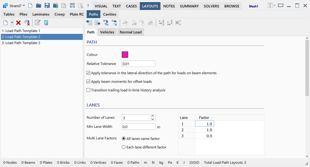
The LAYOUTS: Path sub-tab is divided into two panes: load path template list on the left, and load path data on the right.
Load Path Template List Pane
Situated on the left of the window, it lists the available load path templates.
Data Pane
Situated at the right of the window, it consists of three tabs:
-
Path
Defines path sizes, number of lanes, centrifugal load equations and other factors.
-
Vehicles
Specifies vehicle names, types, direction, velocity and activity.
-
Normal Load
Defines the sizes and magnitudes of vehicular loads in terms of point forces, distributed forces and/or heat sources.
Toolbar Functions
In addition to the common controls, the following functions are available:
Import load path template data
Imports lanes, vehicles and loading information from the load path template library into the currently selected load path template entry.
See Paths: Import/Export Load Path Template Data.
Export load path template data
Exports the lanes, vehicles and loading information from the currently selected load path template entry into the load path template library.
See Paths: Import/Export Load Path Template Data.
Insert vehicle
Inserts a new row of vehicle data before the highlighted cell.
This function is only available in the Vehicles tab.
Add vehicle
Adds a new row of vehicle data to the end of the list.
This function is only available in the Vehicles tab.
Clone vehicle
Duplicates the current row of vehicle data and adds it to the end of the list.
This function is only available in the Vehicles tab.
Delete selected vehicles
Removes the highlighted rows of vehicle data.
This function is only available in the Vehicles tab.
Insert row
Inserts a new row of load data before the highlighted cell.
This function is only available in the Normal Load tab.
Add row
Adds a new row of load data to the end of the list.
This function is only available in the Normal Load tab.
Delete selected rows
Removes the highlighted rows.
This function is only available in the Normal Load tab.
Path tab
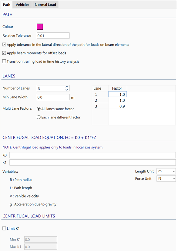
Colour
The colour of the load path template.
Relative Tolerance
Geometric tolerance to determine whether an element lies on a load path.
The actual distance used for these tolerances is this Relative Tolerance value times the Length of the Path.
Apply tolerance in the lateral direction of the path for loads on beam elements
If set, a load on a load path will only be applied to a beam element when the patch of the path intersects the beam element and the beam element is laterally within the specified Relative Tolerance.
If not set, the lateral distance is ignored and therefore the load is applied to the beam element as long as the beam element intersects with the patch on the path.
A patch on a path is an area bounded by the lane width and the path length divided by the number of divisions assigned to the path.
Apply beam moments to offset loads
If set, a path load on a beam element that does not land exactly on the beam element (i.e., a load that is offset from the beam centreline), but which is within the specified tolerance, will be represented as a force-moment pair on the beam (in addition to the force, a moment equal to the force times the normal distance between the force and the beam centreline will be applied to the beam element).
If not set, only the force will be applied to the beam element.
Transition trailing load in time history analysis
If set, continuity of moving load from one path to another connecting path is preserved.
This is applicable to transient dynamic analysis only and does not affect the generation of influence cases.
Number of Lanes
Specifies the number of lanes on the load path.
Min Lane Width
Specifies the minimum lane width.
Some design codes require this. Note that the lane will always be at least as wide as is required to accommodate the defined vehicle description (i.e., to accommodate the defined forces).
Active Lanes / Load Factor
Specifies load factors for design in conjunction with the Multi Lane Factors option below. These are used when generating influence cases (see CASES: Influence Cases) to apply a factor depending on the number of vehicles that generate the worst-case situation.
Multi Lane Factors
-
All lanes same factor
All lanes are factored by the same load factor depending on the number of active lanes.
-
Each lane different factor
Each lane is factored according to the specified load factors based on their severity.
For example, if there are three lanes in the load path template, each with a different type of vehicle, and the factors are defined as 1.0, 0.9 and 0.7 respectively, then the load influence cases will generate the worst case condition based on:
All lanes same factor:
- If only one lane is active, 1.0 times the vehicular loads.
- If two lanes are active, 0.9 times both vehicular loads on both lanes.
- If three lanes are active, 0.7 times all three vehicular loads on all three lanes.
Each lane different factor:
- If only one lane is active, 1.0 times the vehicular loads.
- If two lanes are active, 1.0 times the vehicular loads in the lane that has the greatest effects and 0.9 times the vehicular loads in the other lane.
- If three lanes are active, 1.0 times the vehicular load in the lane that has the greatest effects, 0.9 times the vehicular load in the second-most influential lane and 0.7 times the vehicular load in the third-most influential lane.
Centrifugal Load Equation
Centrifugal loads are generated as a function of the local Fz loads using the equation Fc = K0 + K1 * Fz.
K0 and K1 can be expressed in terms of path radius (R), path Length (L), vehicle velocity (V) and acceleration due to gravity (g).
The Units used in the equation can be specified independently of the units used in the model.
Limit K1
If set, upper and lower limits can be placed on K1.
K1 limits may be required by design standards.
Vehicles tab
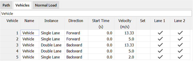
For generating influence cases, specifies the lane/s in which the vehicles can be active and whether any vehicles that can straddle across adjacent lanes.
For transient dynamic analyses, specifies the direction of vehicle travels, the vehicle's velocity and start time. Vehicle's start time can be negative to indicate the amount of head start the vehicle had prior to the simulation time zero (i.e., the vehicle is already partially or completely on the load path lane at the start of the transient simulation).
Normal Load Point Force tab
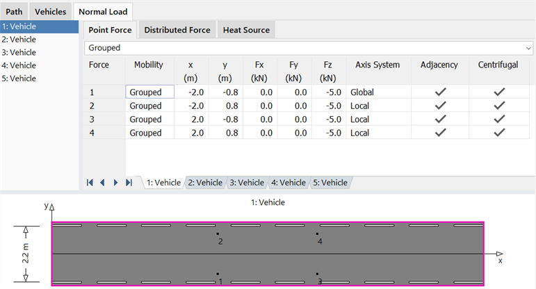
Local coordinates x and y specify the location of a point force on the load path.
Point force components Fx, Fy and Fz can be referenced to either the path's local axis system or the global XYZ system.
The Mobility of a Point Force can be Grouped or Floating.
-
Grouped
Point Forces that are Grouped move together in the lane with fixed relative spacing in the x and y directions.
-
Floating
A Floating Point Force moves independently of any other load and can be positioned at any x or y location in the lane.
Note that for a dynamic analysis, Floating Point Forces are treated as Grouped loads.
If Adjacency is set, multi lane load factors in the Path tab are considered.
If Centrifugal is set, the centrifugal effects specified in the Path tab are considered.
Normal Load Distributed Force tab
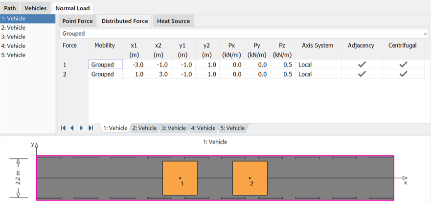
Coordinates x1, x2, y1 and y2 specify the location and area of patches of distributed forces on the load path.
Distributed force components Px, Py and Pz can be referenced to either the path's local axis system or the global XYZ system. The force components are defined as force per length (distance along x). For example, 0.5 kN/m means that 500 N force is applied if the patch footprint is 1.0 m long (size in x), regardless of the patch width (size in y).
The Mobility of a Distributed Force can be Grouped, Leading, Trailing, Full Length or Floating.
-
Grouped
Distributed Forces that are Grouped move together in the lane with fixed relative spacing in the x and y directions.
-
Leading
Leading Distributed Forces extend in the x direction from the maximum x ordinate of all Grouped loads to the end of the Load Path. The y direction extents of a Leading load are defined by ordinates y1 and y2.
-
Trailing
Trailing Distributed Forces extend in the x direction from the minimum x ordinate of all Grouped loads to the beginning of the Load Path. The y direction extents of a Trailing load are defined by ordinates y1 and y2.
Note that the Leading and Trailing forces will extend from the maximum or minimum x ordinate, respectively, of Grouped Point Forces or Heat Sources if the minimum or maximum x ordinates of these loads is greater than the Grouped Distributed Forces.
-
Voids
A void region in a load path can be defined by creating a Grouped distributed load with zero load magnitude. This feature enables the definition of a void area of load that leads and/or trails other grouped loads before the Leading and Trailing Distributed Forces begin.
-
Full Length
A Full Length Distributed Force acts along the entire length of the load path. The y direction extents of a Full Length load are defined by ordinates y1 and y2.
-
Floating
A Floating Distributed Force moves independently of any other load and can be positioned at any x or y location in the lane. Floating distributed forces can only move along the length of the load path.
Note that for a dynamic analysis, Floating Distributed Forces are treated as Grouped loads.
If Adjacency is set, multi lane load factors in the Path tab are considered.
If Centrifugal is set, the centrifugal effects specified in the Path tab are considered.
Normal Load Heat Source tab
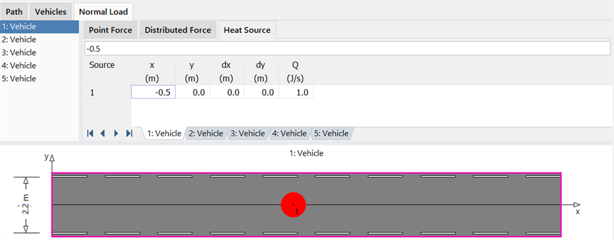
Coordinates x and y specify the heat source location on the load path.
An area can be optionally specified for the Heat Source by lengths dx and dy.
The Heat Source magnitude is specified by Q.
Heat source at a point (i.e., defined over a zero area) is treated as a heat source quantity, whereas a heat source specified over a non-zero area is treated as a heat flux quantity. The total amount of heat energy applied is not affected by the area over which it is applied.
Note that Heat Sources are Grouped loads by default.
See Also