Notes, Warnings and Errors: Dismissible Warnings
Description
Various warnings may be presented in the model window during pre and post processing.
These warnings can be prevented from appearing again by setting the Don't show this warning again option whenever one is shown. Preferences: Warnings offers a range of options for not showing these warnings at all, and for showing them again after they have been dismissed.
List
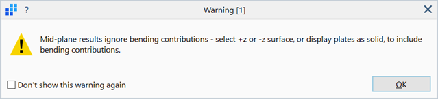
[1]: Mid-plane results ignore bending contributions - select +z or -z surface, or display plates as solid, to include bending contributions.
Stress results on plate/shell elements can be contoured at three locations: the -z surface, the +z surface and the mid-plane. Stress at the mid-plane ignores the effects of bending. When the plate elements are rendered as solid this warning is not relevant because all three surfaces will be shown in the same display.
[2]: Node displacements are much bigger than the overall dimensions of the model - this could indicate an invalid result.
The warning intends to highlight models whereby the displacement results are larger than is typically expected for a structure, particularly in linear analysis. For geometric nonlinear analysis, and for dynamic problems of moving bodies, very large displacements can be reasonable.
[3]: Displacements for linear buckling and natural frequency solutions are not physical displacements. They are normalised values that represent the deformed shape.
This warning is shown when a contour of the node displacements is produced for natural frequency or linear buckling results. The displacements produced for these solutions are not physical displacements, they simply describe the movements of the nodes relative to each other in the vibration or buckling mode. The magnitudes of displacement can be scaled as desired depending on the requirements. By default, Strand7 scales the displacements of the natural frequency mode shapes such that a unit modal mass is recovered when a displacement vector pre and post multiplies the mass matrix used to calculate the modes. It is also possible to scale the displacements of the frequency mode shape such that an engineering modal mass is recovered instead (see Results Options: Displacement Tab).
[4]: Element results for linear buckling and natural frequency solutions are not physical results. They are normalised values that represent result patterns for the observed deformation.
Both the Natural Frequency and Linear Buckling solvers offer the option of producing 'result patterns' such as stress patterns based on the displacements of the mode shapes. These result patterns are not physical results and are intended only to illustrate the stress distributions produced by each mode.
[5]: Combined plate results with spectral solutions require the modal results. Modal results have not been saved in the current spectral solution. Rerun the Spectral Response analysis saving the modal results to obtain combined results.
This warning will only apply if opening a result file generated with a previous Strand7 release that does not include the modal results in the spectral response solution files. Without the modal results, many result quantities cannot be produced. In the current Strand7 release, modal results are always saved in the spectral response solution files, so this warning message will never be produced.
[6]: Combined brick results with spectral solutions require the modal results. Modal results have not been saved in the current spectral solution. Rerun the Spectral Response analysis saving the modal results to obtain combined results.
This warning can only occur with a result file generated with a previous Strand7 release that does not include the modal results in the spectral response solution files. Without the modal results, many result quantities cannot be produced. By re-running the analysis in the current Strand7 release, modal results will be saved in the spectral response solution file and this warning message will not be produced.
[7]: One or more RC layouts contain invalid concrete material parameters.
This warning can be produced when generating a contour plot of a reinforced concrete quantity for reinforcement layouts with invalid concrete material data (LAYOUTS: Plate Concrete Reinforcement (RC)).
[8]: One or more RC layouts contain invalid steel material parameters.
This warning can be produced when generating a contour plot of a reinforced concrete quantity for reinforcement layouts with invalid steel material data (LAYOUTS: Plate Concrete Reinforcement (RC)).
[9]: One or more RC layouts contain invalid reinforcement bar sizes.
This warning can be produced when generating a contour plot of a reinforced concrete quantity for reinforcement layouts with invalid reinforcement bar sizes (LAYOUTS: Plate Concrete Reinforcement (RC)).
[10]: One or more RC layouts contain invalid cover or reinforcement sizes.
This warning can be produced when generating a contour plot of a reinforced concrete quantity for reinforcement layouts with invalid cover or reinforcement bar sizes (LAYOUTS: Plate Concrete Reinforcement (RC)).
[11]: One or more elements contain invalid angles between RC layers.
This warning can be produced when generating a contour plot of a reinforced concrete quantity for plate elements that have invalid angles between reinforcement layers (LAYOUTS: Plate Concrete Reinforcement (RC)). For example, two sets of parallel layers is an invalid layup of reinforcement bars.
[12]: The quadratic RC equation could not be solved in one or more elements. This is usually because the plate thickness is too small for the assigned RC layout or the plate moment is too large.
This warning can be produced when generating a contour plot of a reinforced concrete quantity using the simplified method but the quadratic equation that determines the concrete block size cannot be solved (LAYOUTS: Plate Concrete Reinforcement (RC)).
[13]: The elasto-plastic RC iterations did not converge in one or more elements. This is usually because the concrete strains are too large or the RC layout defines zero bar diameters in one or more layers.
This warning can be produced when generating a contour plot of a reinforced concrete quantity using the iterative method but the iterations did not converge (LAYOUTS: Plate Concrete Reinforcement (RC)).
[14]: The results file is an old format file containing incompatible pipe results. To display pipe stresses, rerun the analysis or open the results in a previous Strand7 release.'
This warning will only apply if opening a result file for a model containing pipe elements generated with a previous Strand7 release. For those results files, pipe stresses will not be available. By re-running the analysis in the current release, pipe stresses and other result quantities will be available.
[15]: One or more elements exceeded the allowable compressive concrete strain. Concrete strain can be reduced by allowing compression reinforcement in the RC Layout. Note also that compressive concrete strain contours can be displayed to help identify regions where the limit has been exceeded.
This warning can be produced when generating a contour plot of a reinforced concrete quantity using the iterative method but the iterations do not converge because the allowable concrete strain has been exceeded (LAYOUTS: Plate Concrete Reinforcement (RC)).
[16]: Beam displacement contours will be approximate since the result file does not contain beam forces. To get accurate beam displacement results rerun the analysis requesting Beam Force/Stress results. Nodal results are not affected.
To generate exact beam displacements, the element forces and moments are required. If these result quantities have not been saved in the result file, beam displacements will be generated assuming a cubic displacement shape for beam elements, irrespective of any element loads applied.
[17]: To get accurate results, rerun the Spectral Response analysis saving the modal results. Results shown are approximate.
This warning can only occur with a result file generated with a previous Strand7 release that does not include the modal results in the spectral response solution files. Without the modal results, many result quantities cannot be produced. By re-running the analysis in the current Strand7 release, modal results will be saved in the spectral response solution file and this warning message will not be produced.
[18]: Combined link results with spectral solutions require the modal results. Modal results have not been saved in the current spectral solution. Rerun the Spectral Response analysis saving the modal results to obtain combined results.
This warning can only occur with a result file generated with a previous Strand7 release that does not include the modal results in the spectral response solution files. Without the modal results, many result quantities cannot be produced. By re-running the analysis in the current Strand7 release, modal results will be saved in the spectral response solution file and this warning message will not be produced.
[19]: When the result case includes a spectral SRSS or CQC case, the spectral result must use the Autosign option for reinforcement results to be available.'
The reinforced concrete results cannot be calculated for a plate element unless the relative sign of the internal forces and moments are known. If reinforcement results are required on a spectral response solution, or on a linear combination of linear static and spectral response results, the spectral response solution must have been run using the Autosign option. The Absolute option cannot be used.
[20]: Shear stress components on tapered beams are approximate.
When plotting shear stress results, or results that require shear stress (e.g., principal stress) those stresses are approximate if the beam is tapered. For untapered beams, the shear stresses are exact insofar as the solution of the Poisson equation over the cross section is exact.
[21]: The Digit Grouping Symbol on this system is the same as the Decimal Symbol. Strand7 will use the space character for the Digit Grouping Symbol instead of the current symbol. Correct your settings using the Regional Settings option in the Windows Control Panel.
For the formatting of floating point number in Strand7, both the decimal symbol and the digit grouping symbols are used. These are taken from the regional settings in Windows. If these two symbols have been set as the same character, this warning message is given and the digit grouping symbol is replaced with a space character.
[22]: When the result case includes a spectral SRSS or CQC case, the spectral result must use the Autosign option for laminate results to be available.
The laminate results cannot be calculated for a plate element unless the relative signs of the internal forces and moments are known. If laminate results are required on a spectral response solution, or on a linear combination of linear static and spectral response results, the spectral response solution must have been run using the Autosign option. The Absolute option cannot be used.
[23]: Reaction MPLs need to be associated with an Entity Set, which defines the elements whose nodal reaction contributions are to be included in the summation. This link has no Entity Set assigned, so it cannot produce a reaction.
This warning indicates that a reaction MPL does not have an entity set containing elements associated with it. As such it cannot be used to calculate force and moment integrals. An entity set can always be assigned or changed in a reaction MPL, even after the solver has been run.
[24]: The graphics card does not fully support the required DirectX functionality. Graphics performance or quality may be impacted.
Strand7 makes use of a number of features provided by the GPU through the DirectX API. Older GPUs may not have all the functionality required by Strand7 for fast and efficient rendering of graphics.
See Also