LAYOUTS: Plate Concrete Reinforcement (RC)
Description
Defines concrete reinforcement layouts that can be assigned to plate elements as attributes for reinforcement design calculations.
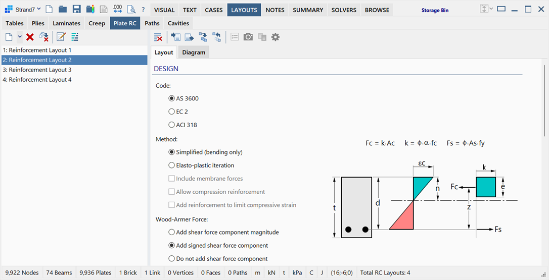
The LAYOUTS: Plate RC sub-tab is divided into two panes: reinforcement layout list on the left, and reinforcement data on the right.
Reinforcement Layout List
Situated on the left of the window, it lists the available reinforcement layouts.
Data and Capacity Pane
Situated on the right of the window, it consists of two tabs:
-
Layout
Selects the design code, calculation method and parameters, and defines the layout geometry and material data.
-
Diagram
Calculates the capacity of the specified reinforcement layout, and displays it as a force-moment interaction diagram.
Toolbar Functions
In addition to the common controls, the following functions are available:
Import RC layout data
Imports design, material and geometry parameters from the reinforcement layout library into the current reinforcement layout. The function can also be executed on multiple reinforcement layouts at once by multi-selecting the layout names in the list: the same data will then be imported into all the selected layouts.
See Plate RC: Import/Export RC Layout Data.
Export RC layout data
Exports the design, material and geometry parameters from the current reinforcement layout into the reinforcement layout library.
See Plate RC: Import/Export RC Layout Data.
Show legend
Shows or hides the graph legend when viewing the interaction diagram in the Diagram tab.
Copy graph image to clipboard
Copies the diagram to the clipboard as an image, when viewing the interaction diagram in the Diagram tab.
Copy data points
Copies to the clipboard as text, the force and moment values used to define the interaction diagram in the Diagram tab.
Graph Options
Opens the Plate RC: Graph Options dialog where graph display parameters (colours, fonts, scale, etc.) can be set when viewing the interaction diagram in the Diagram tab.
Layout tab
DESIGN
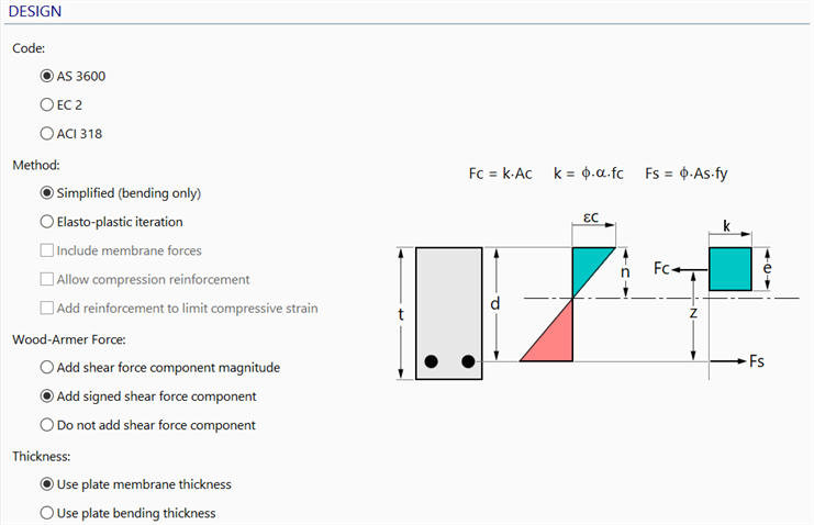
Code
Three options are offered:
- AS3600 (Australian code);
- EC2 (EN1992-1-1 Eurocode); and
- ACI 318 (American code).
The main difference between these is in the way some of the parameters are specified and the nomenclature used. Ultimately the calculation is the same due to the general method used by Strand7. This means that it is possible to use the functionality for most other national codes by using analogous parameters.
Method
-
Simplified (bending only)
The simplified method consists of 3 basic features:
-
It considers only the moments determined from the Wood-Armer equations.
-
It considers only the tensioned steel bars located in the tensile part of the concrete section.
-
It uses a Rectangular Stress Block in the compressive concrete region.
By equilibrating Fc and Fs, the depth of the rectangular stress block is obtained. Then, various other results can be derived, such as the amount of steel required for the given bar spacing.
If the rectangular stress block is not desired, and/or membrane forces are to be considered, and/or compression steel bars are to be considered, the Elasto-plastic iteration method may be selected instead.
-
-
Elasto-plastic iteration
Replaces the rectangular stress block with a bilinear elastic-plastic stress-strain curve for the concrete, determined from the concrete material values Ec and fc. A similar bilinear elastic-plastic stress-strain curve is used for the steel based on Es and fy.
-
Include membrane forces
If set, membrane forces are included in the elasto-plastic iteration.
-
Allow compression reinforcement
If set, reinforcement may be added when the concrete is in compression and the strain exceeds the steel yield strain.
-
Add reinforcement to limit compressive strain
If set, reinforcement may be added when the concrete compressive strain exceeds the allowable limit. This function is only available when compression reinforcement is allowed.
-
Wood-Armer Force
Three calculation options are available:
-
Add shear force component magnitude
If set, Wood-Armer forces are calculated by adding the unsigned (positive) shear force term to the membrane forces in the reinforcement directions.
-
Add signed shear force component
If set, Wood-Armer forces are calculated by adding the signed shear force term to the membrane forces in the reinforcement directions. The sign of the shear force term is taken as the sign of the membrane forces in the respective reinforcement directions.
-
Do not add shear force component
If set, Wood-Armer forces are calculated without adding the shear force term.
See Wood-Armer Forces in Strand7 for more information.
Thickness
As plate/shell elements in Strand7 can have different membrane and bending thickness, this option selects the thickness to use in the reinforcement calculations. Two options are offered:
-
Use plate membrane thickness
-
Use plate bending thickness
Diagram nomenclature
-
t
Full thickness of the slab on which the reinforcement layout is applied. This is usually the same as the plate element.
-
d
Depth from the most compressive concrete fibre to the centroid of the tensile reinforcement.
-
n
Depth from the most compressive concrete fibre to the neutral axis of the reinforcement layout.
-
Fc
Net compressive force carried by the concrete.
-
Fs
Net tensile force carried by the reinforcement.
-
εc
Allowable ultimate concrete strain at the extreme compressive fibre.
-
k
Design concrete strength, inclusive of reduction factors.
-
z
Distance between the line of action of the compressive force resultant and the line of action of the tensile force resultant.
-
e
Depth of concrete region that has reached the compressive strength.
MATERIAL
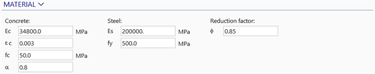
Concrete material data
Defines the material and stress block limits for the concrete.
-
Ec
The modulus of elasticity of the concrete material for design purposes. Note that this value is independent of the modulus defined in the plate properties.
-

The maximum allowable outer fibre compressive strain on the concrete, with a typical value of 0.003 in most Concrete Codes (ACI318, BS8110, AS3600) or 0.0035 in EN1992-1-1. Note that this value usually varies with the concrete strength such as documented in EN1992-1-1.
-
fc
Typically, the characteristic compressive cylinder strength of concrete at 28 days (e.g.,
 in EN1992-1-1 or
  in AS3600 and ACI318).
 -

The strength reduction factor applied to fc to take into account the effects of long-term loading due to maximum compressive stress. This value can vary depending on design applications but has default values of 0.8, 1.0 and 0.85 for AS 3600, EN1992-1-1 and ACI318, respectively. This value may also be comprised of further strength reduction factors if required.
-

(EC2 only) The partial safety factor for concrete with a typical value of 1.2 or 1.5 as specified by EN1992-1-1.
-

(EC2 only) An effective strength factor for concrete that varies with the concrete strength, typically ranging from 0.8 to 1.0 as specified by EN1992-1-1.
Steel material data
Defines the material properties and area limits for the reinforcement.
-
Es
The modulus of elasticity of the reinforcement steel for design purposes.
-
fy
The yield strength of the reinforcement steel (e.g.,
 or
or  in EN1992-1-1 or
  in AS3600). An elastic-perfectly-plastic relationship is assumed for the steel.
 -

(EC2 only) The partial safety factor for reinforcement with a typical value of 1.0 or 1.15, as specified by EN1992-1-1.
Reduction factor
-

Nominal strength/capacity reduction factor of the reinforced layout.
-

Design resistance partial factor as specified by EN1990 that reduces the capacity of the reinforced layout.
Quick functions
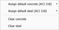
Clicking the MATERIAL header shows a popup menu enabling the selection of typical code-specific concrete and steel data for quick assignment to the reinforcement layout. The options to clear the concrete and/or steel data are also given.
GEOMETRY
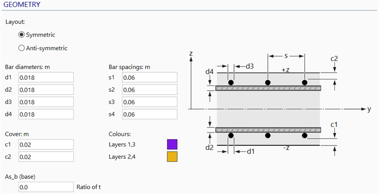
Layout
If Symmetric is set, layer 1 is positioned closer to the -z surface than layer 2.
If Anti-symmetric is set, layer 2 is positioned closer to the -z surface than layer 1.
Bar diameters
Up to four bar diameters may be entered to define the cross section diameters of steel bars from layer 1 to layer 4, illustrated as d1 to d4 , respectively. Layers with a bar diameter of zero are excluded from the calculations.
Bar spacings
Up to four bar spacings may be entered. These define the spacing between steel bars in each individual layer, as illustrated in the figures above. Bar spacing of zero will predict a diameter of zero.
Cover
c1 is the cover on the -z surface and c2 is the cover on the +z surface, as shown in the figures above.
Colours
For checking and identification purposes, the bar directions may be drawn on the plate elements using these colours.
Two colours may be selected, one colour for the bars in layers 1 and 3, and another for the bars in layers 2 and 4.
As_b (base)
The steel reinforcement is represented as a smeared uniform layer of constant thickness, sandwiched between concrete layers. The minimum area of the reinforcement per unit width of slab, usually specified by various concrete codes, is defined as the ratio of equivalent thickness of smeared steel bars, ts, to the concrete slab thickness, t.
Diagram tab
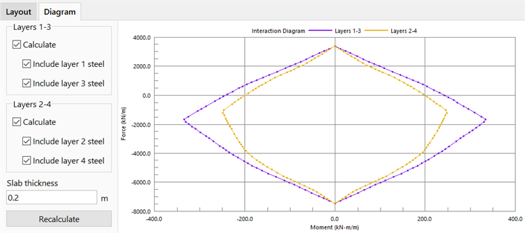
Calculates the bending moment capacity of the defined reinforcement layout for a given concrete thickness as a function of its axial force. The result is a force-moment interaction diagram for interaction in each of the two directions: layers 1-2 and layers 2-3.
Calculate
If set, the capacity in the particular direction of steel reinforcement is calculated.
Include
If set, the particular layer of steel reinforcement is considered for the calculation of capacity.
Thickness
The thickness of the concrete slab that is reinforced according to the current reinforcement layout.
Recalculate
Recalculates and updates the interaction diagram.
See Also