Results Interpretation: Plate RC
Description
The Plate RC module provides several result quantities for plate elements that have Plate Attributes: Concrete Reinforcement (RC) attributed applied.
Wood-Armer Moments
These are moments to be resisted by each layer of reinforcement calculated according to the published equations, which allow designers to make allowance for plate bending and twisting moments when designing the reinforcement within a reinforced concrete panel.
The approach assumes that one direction of reinforcement is aligned with a pre-defined  axis of the plate. The second direction of reinforcement (transverse reinforcement) is defined as being rotated about the plate's local z axis by
  degrees from the
  reinforcement direction according to the right hand rule. The second direction need not be orthogonal to the first (i.e.,
  does not have to be 90 deg).
The approach assumes that one direction of reinforcement is aligned with a pre-defined  axis on the plate. The second direction of reinforcement (transverse reinforcement) is defined as being rotated about the plate's local z axis by
  degrees from the
  reinforcement direction according to the right hand rule. The second direction need not be orthogonal to the first (i.e.,
  does not have to be 90 deg). Note that Strand7 defines both reinforcement directions with respect to the local plate x-axis direction; that is, the first reinforcement direction does not need to line up with the plate element’s local x-axis. Therefore, in a Strand7 model,
  is the angle between the two reinforcement directions, not the angle between the plate local axis and the second reinforcement direction (unless the first reinforcement direction is parallel to the local x-axis).
The equations calculate the moments to be supported by reinforcement placed along the  and
and  directions. These moments are denoted as
  and
and  , respectively.
Strand7 uses the following convention for the moments on a plate element:

 and
and  are direct bending moments and
  is the twisting moment. Note that in the Strand7 convention,
  is not the moment about the x axis, but the moment that produces bending stress in the x direction.
Layers 1 and 2:

If  then set it to zero and ensure that:

If  then set it to zero and ensure that:

Layers 3 and 4:

If  then set it to zero and ensure that:

If  then set it to zero and ensure that:

Advantages of Wood-Armer Moments
Wood (1968) addressed one of the major shortcomings of the so-called "strip method" for design of concrete slabs. As most designers will be aware, there can be large twisting moments in regions near slab corners or column supports. In such cases, design by the strip method is unsatisfactory as twisting moments are ignored. The Wood-Armer equations ensure that twisting moments are taken into account.
Another advantage of Wood-Armer moments is that they are expressed as the moment required to be resisted by a particular layer of reinforcement. So, for each of the four possible reinforcement layers a moment is reported and the user-defined layout is analysed, or an appropriate steel quantity is calculated.
Further, reinforcement need not be orthogonal; skew arrangements can be considered. More often than not, reinforcement will be orthogonal, however there are cases where placing the bars at an angle can avoid unnecessary cutting of the reinforcement, such as with skewed bridge decks.
References
[1] Hillerborg, A. 1953, "Reinforcement of slabs and shells designed according to the theory of elasticity", Betong, vol. 38 no. 2, pp. 101-109. Translation by Gibson, G.N. 1962, Building Research Station, Watford. Library Communication No. 1081.
[2] Wood, R.H. 1968, "The reinforcement of slabs in accordance with a pre-determined field of moments", Concrete, vol. 2, no. 2, February, pp. 69-76.
[3] Armer, G.S.T. 1968, Discussion of "The reinforcement of slabs in accordance with a pre-determined field of moments", Concrete, vol. 2 no. 8, August, pp. 319-320.
The term "Wood-Armer Forces" is not common in the literature, however these forces are a result quantity reported in Strand7. As conventional design of reinforced concrete considers only the moment at a section, the membrane forces in the slab are typically ignored. In Strand7, the Elasto-Plastic Iteration method for RC analysis has the option to consider membrane forces. For consistency, Strand7 applies the same transformation of the plate local membrane forces that are applied to the plate local moments, hence the term "Wood-Armer Forces". These are depicted below:

From the element in-plane (membrane) forces depicted above, and the reinforcement directions  and
and  , the following components are defined for the Wood-Armer forces:

If Add shear force component magnitude is selected, Wood-Armer forces are calculated by adding the unsigned shear force term to the membrane forces in the reinforcement directions:

If Add signed shear force component is selected, Wood-Armer forces are calculated by adding the signed shear force term to the membrane forces in the reinforcement directions. The sign of the shear force term is the same as the sign of the respective membrane forces in the reinforcement directions:

If Do not add shear force component is selected, Wood-Armer forces are calculated without the shear force term:

Note that if multiple layers of reinforcement in the same direction are present, the Wood-Armer Force is evenly distributed amongst those layers for reporting purposes. However, in the calculation of steel requirements that consider the membrane force on a plate element, the full Wood-Armer Force is used. That is, when calculating the steel for layers 1 and 3, the full Wood-Armer force in the  reinforcement direction is considered. Similarly, when calculating the steel for layers 2 and 4, the full Wood-Armer force in the
  reinforcement direction is considered.
Steel Area (As)
Steel area is the required amount of reinforcement for a balanced section supporting the calculated moment and membrane forces (if considered). This result quantity can be calculated at each layer and can be presented in the following ways:
-
Area/Length
The total amount of reinforcement steel required in terms of total cross section area of the steel bars per unit width of slab.
-
Bar Spacing
Spacing between the steel bars for the selected layer based on the nominal bar diameters defined in the LAYOUTS: Plate Concrete Reinforcement (RC).
-
Bar diameter
Bar diameter for the selected layer is calculated based on the nominal bar spacings defined in the LAYOUTS: Plate Concrete Reinforcement (RC).
-
Area/A_slab
The ratio of the reinforcement cross section area to the cross section area of the slab.
-
Area/A_base
The ratio of the amount of reinforcement to the base amount specified in the LAYOUTS: Plate Concrete Reinforcement (RC).
If this value is greater than 1 then the specified base amount of reinforcement, such as that suggested by the design standards or constraints, is not sufficient.
Concrete Strain
This is the concrete strain at the outer surface (i.e., +z or -z of the element), nearest to and in the direction of the selected layer of reinforcement based on the calculated steel area.
For example, layer 1 concrete strain is the concrete strain at the -z local surface of the RC plate element, in the direction of the layer 1 reinforcement while layer 3 concrete strain is the concrete strain on the +z local surface in the same direction.
This is only available for solutions calculated using the elasto-plastic iteration method.
Steel Area (As - As_b)
This is the extra amount of reinforcement required in addition to the base amount of steel specified in the LAYOUTS: Plate Concrete Reinforcement (RC).
If the specified base amount of reinforcement is greater than the required amount calculated, zero (As - As_b) is given.
Steel Stress (User)
This is the stress in the selected layer of steel reinforcement if the user-specified steel area (i.e., the bar diameter and spacing as specified in LAYOUTS: Plate Concrete Reinforcement (RC)) is used.
Concrete Strain (User)
This is the concrete strain at the outer surface (i.e., +z or -z of the element), nearest to and in the direction of the selected layer of reinforcement based on the user-specified steel area (i.e., the bar diameter and spacing as specified in LAYOUTS: Plate Concrete Reinforcement (RC)).
For example, layer 1 concrete strain is the concrete strain at the -z local surface of the RC plate element, in the direction of the layer 1 reinforcement while layer 3 concrete strain is the concrete strain on the +z local surface in the same direction.
This is only available for solutions calculated using the elasto-plastic iteration method.
Concrete Block Ratio
This is the size of the rectangular stress block as a ratio of plate thickness; that is, e / t in the figure below.
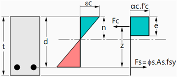
This is only available for solutions calculated using the simplified method.
See Also