Special Topics: Plate RC
Description
The Plate RC module is a design tool to calculate concrete reinforcement results based on plate element forces and moments.
Similarly to the material and section libraries, reinforcement layouts can be manually created, or read from and stored to a reinforcement library. The reinforcement libraries have the extension .REO and are located in the ..\DATA folder of the installed Strand7 directory.
See Properties: Import/Export Materials.
To assign a Plate RC layout to plate elements , use Plate Attributes: Concrete Reinforcement (RC).
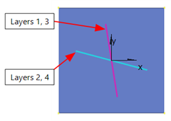
The directions of reinforcement are defined as angles with reference to the plate element's local x axis. Longitudinal and transverse reinforcement do not have to be arranged perpendicular to each other (i.e., skew reinforcement can be considered). The reinforcement directions can be modified by adjusting the angles using Align Tools: Plate RC Directions to UCS or by adjusting the plate element's local axes using Align Tools: Plate Axes to UCS or Plate Attributes: Local Axis Angle.
As the Plate RC module is a post-processing tool, relevant results can be obtained without re-running a solver. Some of the results available from the Plate RC module includes:
- Wood-Armer Forces and Moments, which combine and transform relevant actions on the plate elements, including twisting moments, into effective force and moment quantities for respective reinforcement layers.
- Required design reinforcement area/length, spacing and bar diameter.
- Concrete strain.
- Reinforcement stresses.
- Force-moment interaction diagram of the specified Plate RC layout.
See Results Interpretation: Plate RC.
Iterative Solution of Reinforced Concrete
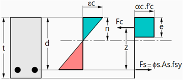
For the Simplified (bending only) method, which assumes a rectangular concrete stress block as shown below, the main calculation procedure is:

where  is the Wood-Armer moment for a particular reinforcement layer. Solving the quadratic equation gives
  , which then allows other result quantities to be calculated.
If the rectangular stress block is not desired, and/or membrane forces are required, and/or compression reinforcement is required, the Elasto-plastic iteration method is more appropriate. This method replaces the rectangular concrete stress block with a bilinear elasto-plastic stress-strain relationship determined from the specified concrete material modulus and strength.
The nonlinear material behaviour of a steel reinforced concrete slab, where the steel is represented as a smeared uniform layer of constant thickness, can be determined by using a layered analysis approach. The slab is divided into a number of thin layers with each layer being either concrete or steel, depending on the reinforcement layout; each layer references the appropriate stress-strain relationship.
This approach allows us to consider the simultaneous application of both membrane and bending loads on the reinforced plate.
Note that if the Plate RC layout sets the bar diameter to zero for any layers, the Elasto-plastic iteration method does not place steel on those layers; the final reinforcement solution will rely on steel being placed only on the layers where a non-zero bar diameter has been specified. A non-zero bar diameter therefore signals to the algorithm that steel may be placed there, but the amount of steel to be placed is determined by the algorithm as described below (i.e., by the Plate RC module).
The constitutive equation for the slab and concrete composite can be described by:

where:

is the resultant force vector, which has units of force per unit length, and

is the resultant moment vector, which has units of moment per unit length.  and
and  are obtained from the finite element structural solution as stress and moment resultants on the plate element.
 is the extensional stiffness matrix (membrane elasticity matrix) defined by:

 is the bending stiffness matrix defined by:

and  is the extensional/bending coupling matrix defined by:

where  is the elasticity matrix for layer
  (which may be either concrete or steel), and the matrices
  ,
,  ,and
,and  are symmetric.
In the above summations,  is the number of layers.
 is the mid-plane membrane strain vector and
  is the plate curvature vector.
In the case of nonlinear material behaviour (both concrete and steel),  is a function of the strain in the layer, leading to a set of nonlinear equations, which may be solved using standard Newton-Raphson iteration.
Note that although each ply in the reinforced concrete composite may exhibit nonlinear stress-strain behaviour, the assumption of linear strain variation through the composite slab thickness is made.
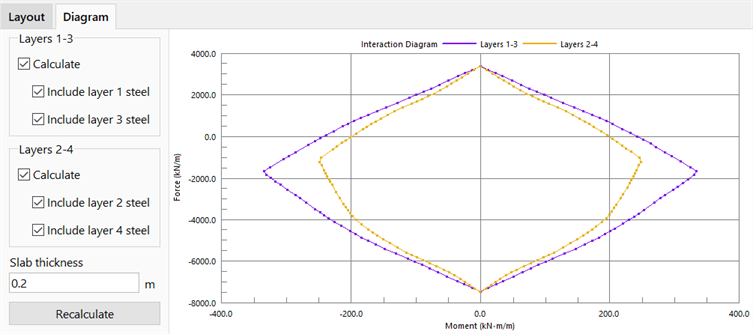
Force-Moment Interaction Diagram
By specifying the bar diameters, spacing, cover thickness, slab thickness and material property, a force-moment interaction diagram can be generated. The diagram shows the section's bending moment capacity as a function of coexisting axial force.
See Also