Align Tools: Plate Axes to UCS
Description
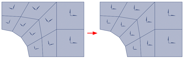
Aligns local axes of selected plate elements with an axis of the specified coordinate system.
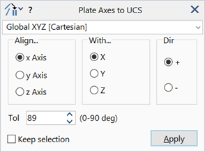
Dialog
Coordinate System
The coordinate system (UCS) in which the alignment reference axis is defined.
Align...
Local plate axis to be aligned.
The axis will be one of the local (x,y,z) axes.
With...
Reference axis of the specified UCS to which the plate axis is aligned.
Dir
The direction of the aligned plate axis with respect to the reference axis.
- + aligns the plate axis to the positive direction of the reference axis.
- – aligns the plate axis to the negative direction of the reference axis.
Tol
An angle in degrees.
When aligning a plate's x and y axes, the element will be considered for alignment as long as the angle between the reference axis and the plane of the plate is less than this value.
This tolerance can be used to exclude plate elements that are perpendicular, or nearly perpendicular, to the reference axis. In the perpendicular case, the axes of the plate cannot be aligned with the reference axis. This is because the axis alignment is achieved by rotating the axes about the plate's z axis.
When aligning the z axis of the plate, the alignment can only be satisfied in a general sense because the z axis can only be changed by 180 degrees (by inverting the node connection order to flip the element). If the plate z axis is perpendicular to the reference axis, the z axis cannot be aligned.
The perpendicular cases correspond to a Tol angle of 90 degrees on the dialog. The default value of 89 degrees allows most practical situations to be aligned.
Common Controls
Common Uses
The orientation of the local axes is important as it determines the direction of the local output stresses, moments and forces. The axes are also used for orientating orthotropic and laminate materials, amongst others, and for the application of surface loads. The local axis systems of entire plate meshes usually need to be aligned in a common and consistent direction.
See Also