Align Tools: Beam Axes to UCS
Description
Aligns local or principal axes of selected beam elements with an axis of the specified coordinate system.

Dialog
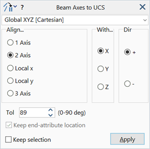
Coordinate System
The coordinate system (UCS) in which the alignment reference axis is defined.
Align...
Beam axis to be aligned.
The axis will be one of the local (x,y) or principal (1,2,3) axes.
With...
Reference axis of the specified UCS to which the beam axis is aligned.
Dir
The direction of the aligned beam axis with respect to the reference axis.
- + aligns the beam axis to the positive direction of the reference axis.
- – aligns the beam axis to the negative direction of the reference axis.
Tol
An angle in degrees.
When aligning a beam's lateral axes, the element will be considered for alignment as long as the angle between the reference axis and the plane of the beam's lateral axes is less than this value.
This tolerance can be used to exclude beam elements that are parallel, or nearly parallel, to the reference axis. In the perfectly parallel case, the lateral axes cannot be aligned with the reference axis. This is because the lateral axis alignment is achieved by rotating the axes about the beam's 3 axis.
When aligning the 3 axis of the beam, the alignment can only be satisfied in a general sense because the 3 axis can only be changed by 180 degrees (by inverting the node connection order to flip the element). If the beam's 3 axis is perpendicular to the reference axis, the 3 axis cannot be aligned.
The perfectly parallel case for lateral axis alignment, and the perfectly orthogonal case for 3 axis alignment, both correspond to the angle of 90 degrees. The default value of 89 degrees allows most practical situations to be aligned.
Keep end-attribute location
Retains the location of end-attributes where the axial direction of an element is flipped due to the alignment operation (that is, the end-attributes of a flipped element are swapped to place them at their geometric location prior to the flip).
End-attributes include beam connection UCS, end releases, heat transfer attributes, response variables, end and side attachments.
Common Controls
See Also