Beam Elements: Local and Principal Axes
Description
Two axis systems are used on the cross section of beam elements, the local axes and the principal axes.
The local axes represent the x,y system in which the section is defined; for standard cross sections, these axes are parallel to major flat faces or other geometric features. The origin of the local x, y axes is located at the lower left corner as defined in Properties: Beam Cross Section Shape, except for user-defined BXS beam sections (see Utility: Make BXS) on which the local axes are at the origin of the source mesh.
The principal axes represent the major and minor axes of the cross section and are denoted as the 1 and 2 axis directions. The origin of the principal axes coincides with the centroid position of the cross section.
For symmetric standard sections, where the principal axes are always parallel to the local axes, the 1 axis direction is always parallel to x and the 2 axis direction is always parallel to y. There is no requirement that the 1 and 2 axes be the major and minor axes, respectively; this will depend on the dimensions of the cross section.
For non-symmetric standard sections and for BXS sections, the 1 axis is the major axis and the 2 axis is the minor axis.
To complete the axis systems, the 3 axis is used to denote the axial direction with reference to the principal axes, while the z axis is used to denote the axial direction with reference to the local axes. The 3 axis and the z axis are always the same.
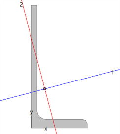
An example inverted angle section is shown below, illustrating its local x, y axes and principal 1, 2 axes.
Default Orientation
A beam element is defined by nodes N1 and N2 as shown below:
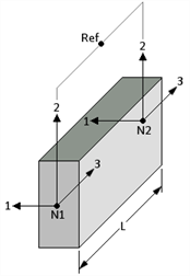
For a beam with a reference node (i.e., a Beam3), the default principal axis system (1,2,3), is defined as follows:
- the 3 axis is directed from node N1 to node N2;
- the 2 axis is normal to the 3 axis and lies in the plane formed by nodes N1, N2 and the reference node RefN. It is positive towards the side on which node RefN lies; and
- the 1 axis completes the right hand axis system.
For a beam without a reference node (i.e., a Beam2), the default principal axis system (1,2,3), is defined as illustrated in the following figure.
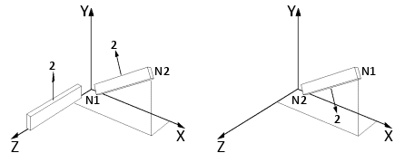
If the beam is parallel to the global Z axis (left image), the 2 direction is always in the positive global Y direction.
If the beam is not parallel to the global Z axis, the 2 direction is given by the vector cross product of the global Z axis and a vector defined by nodes N1-N2. The 3 direction is directed from node N1 to node N2, with the 1 direction completing a right hand system.
After the default axis system has been defined, for either a Beam2 or a Beam3, the following methods can be used to realign or change the orientation of the beam principal axes in a model:
- By using Align Tools: Beam Axes to UCS.
- By assigning a Beam Attributes: Principal Axis Angle.
If a node to which a beam element is connected is moved by any modelling operation, the beam axes are rotated according to the node movement to effectively apply the same movement to the axes instead of reapplying the cross-product convention after moving a node. This means that beam elements may automatically acquire a principal axis angle attribute during the various modelling operations.
Principal and Local Planes
Shear force and bending moment results on beams are available with respect to the two principal planes (parallel to the 1 and 2 axes) or with respect to the two local planes (parallel to the x and y axes).
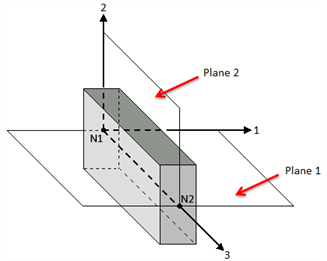
Plane 1 is defined by the principal 1 and 3 axes; plane 2 is defined by the principal 2 and 3 axes.
Shear forces in plane 1 are reported as Shear-1 while shear forces in plane 2 are reported as Shear-2. Similarly, bending moments in plane 1 are reported as Moment-1 while bending moments in plane 2 are reported as Moment-2. That is, Moment-1 is not the moment about the 1 axis, but the moment in plane 1.
Similarly, plane x is defined by the local x and z axes, while plane y is defined by the local y and z axes.
Shear forces in plane x are reported as Shear-x while shear forces in plane y are reported as Shear-y. Similarly, bending moments in plane x are reported as Moment-x while bending moments in plane y are reported as Moment-y. That is, Moment-x is not the moment about the x axis, but the moment in plane x.
See Also