Properties: Beam Cross Section Shape
Description
Used to visualise and define the cross section assigned to the beam property.
Shape Tab
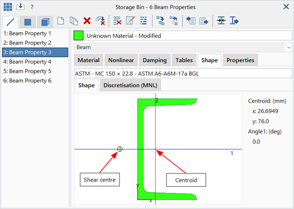
Provides a visual representation of the cross section geometry.
The position of the centroid and shear centre are identified together with the orientation of the local (x,y) and principal (1,2) axes.
Click the image to open the Beam Cross Section Selection dialog (see Properties: Beam Cross Section Selection).
Discretisation (MNL) Tab
Provides a visual representation of the discretisation used by the nonlinear solvers when material nonlinearity is considered. Stresses are evaluated at each grid point shown in the image. The cells are used to integrate the beam section properties and the force/moment resultants.
Available only for the Beam element type.
Divisions
Number of divisions used for the cross section discretisation.
Some section types offer only a Nominal Divisions option (e.g., BXS and BGL sections) while other sections offer the option to specify the divisions separately in the x and y directions, in addition to a nominal option.
The Nominal option works as follows:
The requested number of divisions is applied to the longer of the x and y dimensions of the cross section. The number of divisions along the short dimension is then automatically set based on the ratio of these dimensions. In either direction, the actual number of divisions produced might not match the set value precisely. The are a number of considerations made about the discretisation such as symmetry, through thickness division requirements, element aspect ratio and section shape. Therefore, the value requested should be considered as a hint rather than an absolute request.
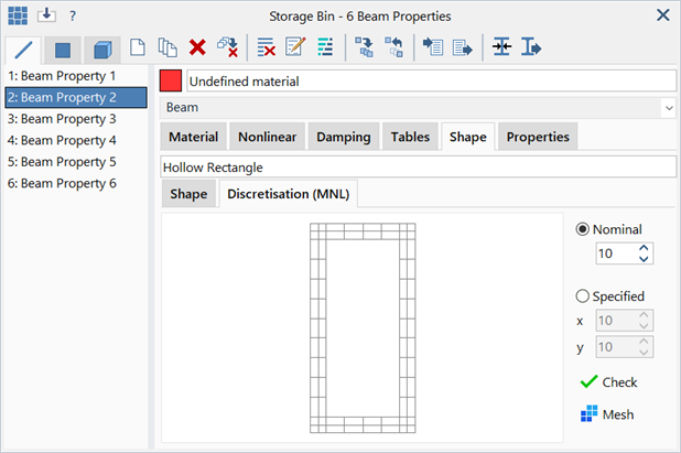
For example, in the standard rectangular hollow section shown above, a nominal division setting of 10 produces nine divisions along the vertical (longer) edges, plus two effective divisions in the thickness direction of the horizontal edges, which are further divided into two sub-divisions. In the horizontal direction, there are four divisions along the edges, plus again, two effective divisions in the thickness direction of the vertical edges, which are also further divided into two sub-divisions.
The Specified option works similarly to the Nominal option in that the values requested are considered as hints, not as absolute requests. However, the Specified option offers greater flexibility to increase the number of divisions, particularly if more divisions are required along the shorter direction.
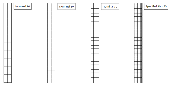
In the following image, a relatively thin rectangular solid cross section is discretised at three nominal levels (10, 20 and 30). These discretisations are suitable for a material nonlinear analysis where nonlinear material behaviour is primarily due to bending about the major axis. However, if material nonlinear behaviour is due to bending about the minor axis, even the nominal 30 setting might be too coarse a discretisation (only three divisions are produced along the shorted edge). By using a specified setting of 10 x 30 divisions, more layers are defined across the shorter edge.
Note that if no material nonlinearity occurs during the analysis, then even the coarsest discretisation will produce the exact results.
When the divisions are changed on an arbitrary BXS section, particularly a BXS with high aspect ratio elements, division settings do not always produce a compatible mesh (a compatible mesh is not a requirement for the use of the discretised section in material nonlinear analysis, but it is a requirement for the initial mesh used to define the BXS to start with).
For a BXS, the requested division parameter is used as follows:
A nominal section dimension is calculated as the longest x or y dimension of the bounding box of the cross section; this section dimension, divided by the number of nominal divisions, gives a desired edge length. Elements with edge lengths greater than 1.5 times the desired edge length are subdivided. As the subdivision number must be a whole number, the number of divisions applied to an element edge is the ratio of the element edge length and the desired length, rounded to the nearest integer.
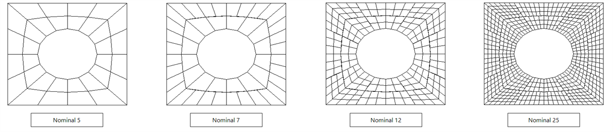
The following image illustrates different nominal divisions for a BXS produced with a relatively coarse initial mesh. As the number of divisions increases, different elements are subdivided, depending on their edge lengths. Although the initial mesh used to produce the BXS must be a compatible mesh in order to compute the correct shear stress coefficients, the subdivided mesh need not be compatible. This is because the subdivided mesh is not used to calculate coefficients; it is used only to interpolate a coefficient map over the section from the coefficient field calculated with the initial (compatible) BXS mesh.
Check
Runs a quality check on the discretisation.
Unit shear forces and torque are applied to the section. The stresses calculated using the interpolated coefficients from the section discretisation are integrated to compute the forces and torque. The ratios of the calculated values to the applied values are reported. Ratios close to 1.0 indicate a good quality discretisation, while ratios away from 1.0 indicate a poor quality one. Generally, increasing the number of divisions will improve the result. If the result does not improve with increasing discretisation, it usually indicates that the initial mesh used for the BXS is not of sufficient quality.
Creates a new St7 file containing a plate mesh of the cross section at the requested discretisation.
See Also