Properties: Beam Cross Section Selection

Description
Defines beam cross section shapes parametrically, or selects them from the various cross section libraries.
The properties of selected sections are automatically calculated, or retrieved from a library, and assigned to the beam property.
Section Selection Dialog
Standard Sections
Fifteen standard sections are available. Dimensions of standard sections are specified in the Shape tab to define the simplified geometry representing each shape.
Section properties calculated for these sections (e.g., second moments or area, torsion constant, and so on) will not include features such as fillets, radii or flange taper.
Fibre stress calculated on these sections will be of acceptable accuracy for most analysis requirements. Shear stresses (due to shear forces and/or torque) are available for these simplified sections. However, in the vicinity of 90 deg corners (e.g., at the junction between the web and flange of an I-beam) shear stresses will be approximate due to the stress singularity at the corner. Away from the corner, reasonable shear stresses will be calculated.
Beam Section Library (BSL)
Opens the Import Beam Section dialog to import a section from the Beam Section Library (BSL). See File Formats: Beam Section Library.
The BSL contains sections data from a large range of international catalogues and collections. The geometry defining these section shapes is simplified with features such as fillets, radii and flange taper not included. However, the geometric properties of the sections (e.g., second moments or area, torsion constant, and so on) stored in the libraries and used for analysis, are those for a section that includes all the geometric features.
Fibre stress calculated on these sections will be of acceptable accuracy for most analysis requirements. Shear stresses (due to shear forces and/or torque) are available for these sections. However, in the vicinity of 90 deg corners (e.g., at the junction between the web and flange of an I-beam) shear stresses will be approximate due to the stress singularity at the corner. Away from the corner, reasonable shear stresses will be calculated.
See Import Beam Section Dialog.
Beam Geometry Library (BGL)
Opens the Import Beam Section dialog to import a section from the Beam Geometry Library (BGL). See File Formats: Beam Geometry Library.
The BGL contains detailed section data and geometry from a large range of international catalogues and collections. The geometry defining these section shapes may include features such as fillets, radii and flange taper, amongst others. For this reason, these sections are preferred for models where accurate cross section shear stress (due to shear forces and/or torque), is required over the entire section.
See Import Beam Section Geometry Dialog.
User Defined Section (BXS)
Opens the file browser dialog to locate and select a Beam Cross Section (BXS) file. See File Formats: BXS File.
BXS files are user defined cross sections generated from plate meshes. See Utility: Make BXS.
Shape Tab
Dimensions
Dimensions of the selected standard section such as radius, height, width and thickness.
The dimensions of BSL, BGL and BXS sections cannot be modified.
Assign Shear Areas
If set, the shear areas of the section are assigned to the beam property, thereby enabling the thick-beam implementation of the beam element.
If not set, the shear areas are set to zero, thereby enabling the thin-beam implementation of the beam element. See Shear Areas (A1 / A2).
Mirror Options Tab
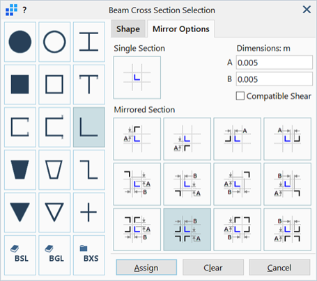
List of mirroring options available to generate composite sections from the standard section shapes except for solid circle and hollow circle. BGL and BXS sections cannot be mirrored. BSL sections cannot be mirrored directly, but they can be converted to an equivalent standard section and then mirrored. To convert a BSL to a standard section, click the appropriate section shape icon after importing the section from the library; this will activate the Mirror Options tab enabling the section to be mirrored.
Twelve different mirroring configurations are available.
Dimensions (A / B)
Dimensions that specify the offset of the mirrored sections from each other.
Offsets are visually depicted on the icon of each mirroring configuration.
Compatible Shear
This option sets whether shear compatibility is to be maintained at the connection between individual sections that comprise the mirrored section. It affects the calculation of the torsion constant, the shear areas and the shear centre. It has no effect on the calculation of geometric properties such as cross section area and second moments of area.
If set, the shear related properties of mirrored sections are calculated assuming that the individual sections act together as one composite section (i.e., they are rigidly connected), irrespective of the gap size.
If not set, the shear related properties of the section are calculated assuming that each section is independent. The shear areas and torsion constant are then simply taken as the sum of the respective individual sections, and the shear centre will be placed at the section centroid. Shear stress due to shear forces and/or torque is still available.
See Also