SOLVERS Home: Harmonic Response
Description
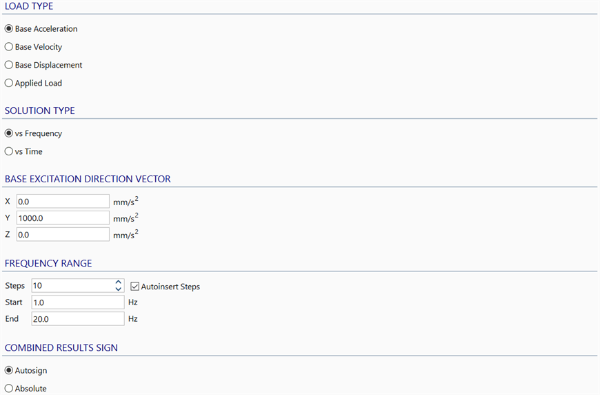
Solver parameters relevant to the Harmonic Response solver.
LOAD TYPE
The three base excitation types do not include any other loads applied to the model. That is, node and element attributes (e.g., point force, pressure) and global accelerations (as defined in CASES: Load Cases) are ignored. The excitation is fully described by the direction vector. The base is taken to be the restrained nodes in the model.
Base Acceleration
The excitation is a sinusoidal acceleration at the base of the structure in the specified direction.
Base Velocity
The excitation is a sinusoidal velocity at the base of the structure in the specified direction.
Base Displacement
The excitation is a sinusoidal displacement at the base of the structure in the specified direction.
Applied Load
The excitation comes from load attributes assigned to nodes and elements, and from global accelerations (as defined in CASES: Load Cases). The loads are applied sinusoidally to the structure. Load factors, relative phase angles and load frequencies can be specified for each load case via the Load sub-tab.
SOLUTION TYPE
The Harmonic Response solver offers two solution types.
vs Frequency
In this solution type, frequency refers to the frequency of the excitation (base or load). This solution type produces a result file with one result case for each excitation frequency over the specified range. In each result case, all the excitations are applied together at the same frequency, each with a specified relative phase angle, to produce the combined result.
vs Time
In this solution type, results are available as a time history of response, similarly to a transient dynamic analysis (Solvers Background: Linear Transient Dynamic).
For base excitation, only one of which can be applied at any one time, the excitation is applied at a specified frequency. This produces a single result case in the result file containing the magnitude and phase angle of every result quantity calculated. From these results, the post-processor can produce a time history response of any result quantity (see CASES: Harmonic Time).
For applied load excitation, each load case can be applied at its own frequency and relative phase angle. This produces a result file with one result case for each included load case containing the magnitude and phase angle of the result quantities calculated. From these results, the post-processor can produce a time history response by combining and factoring the results of each included load case (see CASES: Harmonic Time).
BASE EXCITATION DIRECTION VECTOR
Specifies the direction and magnitude of the excitation for the three base excitation load types.
The direction vector is not normalised. It is a vector with physical units that depend on the base excitation type. These units are length/s2 for base acceleration, length/s for base velocity and length for base dispalcement.
This direction vector is not used when Load Type is Applied Load.
FREQUENCY RANGE
For the vs Frequency solution type, the following parameters are relevant:
Steps
Specifies the number of result cases to be generated between Start and End frequencies.
-
Autoinsert steps
If set, additional steps are automatically added at each of the natural frequencies and half-power points within the specified frequency range (i.e., up to three extra result steps for each mode frequency within the range).
If not set, no additional steps are added and the result file will contain as many result cases as the specified Steps.
Start
Specifies the lower bound of the excitation frequency range.
End
Specifies the upper bound of the excitation frequency range.
For the vs Time solution type with base excitation, only the following parameter is relevant:
Start
Specifies the base excitation frequency.
For the vs Time solution type with applied load excitation, none of these parameters is relevant.
COMBINED RESULTS SIGN
This option is not relevant to the vs Time solution type. When using vs Time, the results for each excitation or load case are calculated in the form of a vector of magnitudes of response (i.e., all absolute values) together with a vector of corresponding phase angles. From these two quantities it is possible to calculate the equilibrium response at any time; this is performed by CASES: Harmonic Time, which generates equilibrated and signed results.
When using the vs Frequency solution type, the results produced at each excitation frequency are the maximum magnitudes of the total response all shown together in the one result case. For these results, the sign is not relevant because the maximum responses for all quantities do not generally occur at the same time for harmonic excitation. However, for the purpose of graphical visualisation of results, two options are given for the sign of the results.
Autosign
The sign of each result quantity in the combined response is set as the sign of the mode with the largest modal contribution to that result.
Absolute
All results are given positive signs.
See Also