Node Attributes: Rotational Stiffness
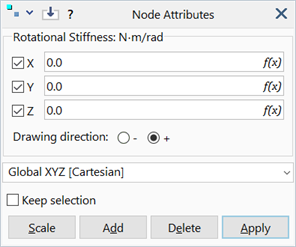
Description
Assigns rotational stiffness to selected nodes using three orthogonal principal components and a coordinate system.
Rotational stiffness attributes are freedom case dependent.
Dialog
Rotational Stiffness X / Y / Z
Three principal components of a rotational stiffness matrix defined in the selected coordinate system.
Drawing Direction
The direction in which the attribute symbol is drawn along the axes.
The drawing direction is used only for graphical display purposes and does not affect the stiffness.
Coordinate System
The coordinate system (UCS) in which the principal rotational stiffness components are defined.
The rotational stiffness attribute remains associated with the UCS in which it is defined. Subsequent changes to the UCS will change the resulting stiffness matrix.
In geometric nonlinear analysis, the principal directions of the attribute's stiffness matrix are not updated.
Common Controls
Units
Force×Length/Angle (e.g., N.m/rad, lbf.in/rad).
See Also