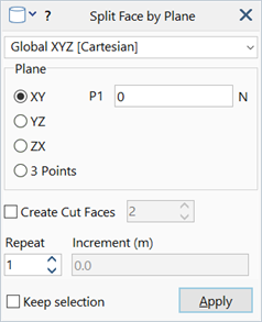
Geometry Tools: Split Face by Plane

Description
Splits selected faces on a plane defined by a UCS and a single point, or by three points.
A one-point UCS plane may use 0 as the point, which places the plane at the origin of the selected UCS.

Dialog
Coordinate System
Coordinate system (UCS) used to define the cutting plane.
Only Cartesian planes may be selected.
Plane
Defines the cutting plane. Two options are available:
-
XY / YZ / ZX
Cutting plane passes through point P1 and is parallel to a principal plane of the selected UCS.
If P1=0 the plane passes through the origin of the selected UCS.
-
3 Points
Cutting plane passes through three points P1, P2 and P3. All three must be non-zero
P1 / P2 / P3
Points used to define the position of the cutting plane.
Create Cut Faces
When set, additional faces are created on the cutting plane to fill any closed sequence of cut edges.
Count specifies the number of faces to generate, which may be one or two. Setting count to two creates duplicate overlapping faces with opposing normals, which facilitates the definition of two connected solid parts.

Repeat
Specifies the number of parallel splits to make. The direction and distance between splits is specified using Increment.
Increment
Distance between repeated splits. A positive increment is in the direction of the 3 axis of the cutting plane, as defined using the right hand rule.
Common Controls
See Also