Mesh Tools: Solid Automesh from Plates
Description
Automatically generates a solid mesh of tetrahedral brick elements from plate mesh boundaries defining the surfaces of closed volumes.
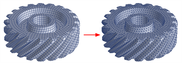
The plate mesh must define a water-tight (i.e., manifold) surface for each solid. This means that every edge of every plate element in the mesh must be shared by exactly two plate elements. Plate meshes containing free edges or T-junctions cannot be used for solid meshing.
Brick faces on the resulting solid mesh will be compatible with Tri3 and Tri6 plate meshes used to define the boundary. However, Quad4, Quad8 and Quad9 plate meshes may also be used to define the volume; quadrilateral elements will be automatically split into pairs of triangular elements by the solid automesher.
Multiple volumes can be meshed together. Each volume is treated as a separate entity. If multiple, separate volumes are found in one group, each part is treated as separate solid as long as one does not contain the other. When one part is contained within another, the internal part is automatically detected and treated as a void in the meshed solid.
Plate meshes in different groups can also be meshed independently as separate parts.
Dialog - Elements Tab
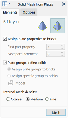
Brick type
Type of tetrahedral brick to generate.
This can be either Tet4 or Tet10, irrespective of the type of plate elements used for the boundary mesh.
If Tet4 is selected, only the corner nodes of the plate elements are used, and therefore linear and quadratic plate meshes will produce the same tetrahedral mesh.
If Tet10 is selected, mid-side nodes will be generated. The mid-side nodes of internal tetrahedra always remain at the linear mid position (i.e., internal tetrahedra have straight edges). The mid-side nodes of surface tetrahedra will either come from the plate mesh itself when it consists of quadratic plate elements (Tri6, Quad8, Quad9), or will be generated as required when it consists of linear plate elements (Tri3, Quad4).
If the plate mesh consists of linear elements, the mid-side nodes of Tet10 elements on the surface of the solid will be positioned at the average of the corner nodes, thereby producing flat Tet10 elements even on the surface.
If the plate mesh consists of quadratic elements, the mid-side nodes of Tet10 elements on the surface of the solid will either use the mid-side nodes on the plate elements directly, or create a new node on the surface of the plate elements (e.g., when splitting a Quad8 to produce two Tri6 elements a new node is required along the diagonal of the Quad8). The surface curvature of the Tet10 mesh will then match the curvature of the plate elements. An exception to this is when the local plate mesh curvature is concave and too small compared with the dimensions of the element (e.g., a small fillet modelled with a curved surface element that is too large). In this situation, the mid-side node on the surface Tet10 might not lie on the surface of the plate element, but might be moved off the surface slightly to avoid an invalid brick element.
Assign plate properties to bricks
If set, the generated bricks are assigned the property type that most frequently appears in the plate mesh boundary of each solid. In the typical case where all plate elements on the surface of a solid boundary are of the same property, the solid elements will also be of that property.
If not set, the property type is assigned sequentially for each solid, as defined by the two following settings.
-
First part property
Property type to assign to the first solid meshed.
-
Next part property
Increment of the property type to assign to each solid meshed.
Plate groups define solids
If set, the solid mesher will mesh plate elements separately according to their group. Plate elements in each group must define a valid boundary mesh to be considered as a separate part. Brick meshes will then be assigned to the group used to define the boundary plate mesh.
If not set, all candidate plate elements will be considered at the same time. The bricks will then be assigned to a group based on the option selected below.
-
Assign plate groups to bricks
Generated bricks are assigned to the group that most frequently appears in the plate mesh boundary of each solid. In the common case where all plate elements on the surface of a solid boundary are in the same group, the solid elements will also be placed in that group.
-
Assign specific group to bricks
Sets the target group to which the generated bricks are assigned. See Global: Groups.
Internal mesh density
Desired internal element size. The surface mesh, to a large extent, dictates solid meshing, so it is possible that some surface meshes will produce identical solid meshes for all three options.
-
Coarse
Attempts to transition to the maximum element size in the minimum number of steps.
Maximum element size is based on the largest plate edge length in the boundary mesh.
-
Medium
More gradual transition is used relative to the coarse mesh.
-
Fine
Minimal transitioning is used.
Dialog - Options Tab
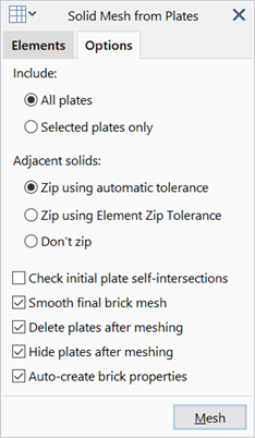
Include
Candidate plate elements to use when solid meshing.
-
All plates
All visible plate elements in the model are considered.
-
Selected plates only
Only selected visible plate elements are considered.
Adjacent solids
-
Zip using automatic tolerance
If set, adjacent solids are zipped using a zip tolerance based on the element edge lengths on the surface of the solid.
-
Zip using Element Zip Tolerance
If set, adjacent solids are zipped using the specified zip tolerance under Tool Options: Tolerance Tab.
-
Don't zip
If set, adjacent solids are not zipped.
Check initial plate self intersection
If set, the initial plate mesh is checked for self-intersection.
Self-intersecting boundary meshes will result in a failure or a poor quality mesh. This check helps to identify where the self-intersection is occurring.
Smooth final brick mesh
If set, the generated brick mesh will be adjusted where possible to improve the internal angles on faces and the angles between faces of the tetrahedra.
Delete plates after meshing
If set, plate elements used for the boundary mesh will be deleted automatically after solid meshing.
Hide plates after meshing
If set, plate elements will be hidden after meshing.
Auto-create brick properties
If set, a new property set is automatically created whenever a generated brick mesh is assigned a new property number.
When multiple parts are found during solid meshing, the following options are given:
See Also