Mesh Tools: Surface Automesh
Description
Automatically generates a surface mesh of plate elements on face geometry.

When meshing multiple faces, the tool ensures that common edges have the same edge subdivision, resulting in a compatible mesh.
The surface automesher aims to generate a uniform mesh of elements with the requested maximum edge length, while accommodating additional constraints such as small features and the various meshing attributes that may have been requested.
Attributes applied on vertices, edges and faces are automatically inherited by the generated node and plate elements. Groups and element sets are also inherited.
Beam elements are generated on edges with the Edge Attributes: Edge Beam attribute applied.
Beam or link clusters are generated on edges with the Edge Attributes: Edge Cluster attribute applied.
Dialog - Sizes Tab
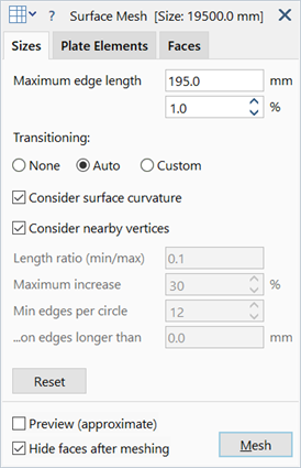
Maximum edge length
Maximum edge length of generated plate elements.
May be set as an absolute size in length units, or as a percentage of the nominal model size. Either parameter may be set, and the other will automatically change to match.
Transitioning
Additional controls used to constrain the element edge lengths.
-
None
Automesher will attempt to transition immediately to the maximum edge length from smaller elements, irrespective of small edges and other features. This usually leads to a more uniform mesh, but local detail at small features and edges with small radii may be skipped.
-
Auto
Automatically determines appropriate values for meshing controls, which are described below.
Edge lengths will transition gradually from smaller elements towards the maximum edge length requested. Features and edges that are smaller than the maximum edge length will influence the local mesh size, and their effect will propagate a certain distance from the feature itself.
-
Custom
Provides for more detailed control of the meshing as described below.
Consider surface curvature
If set, the average surface curvature at the edges of the face is considered in addition to other edge constraints for the generation of plate elements. The curvature constraint is applied to the edges and to the face.
Consider nearby vertices
If set, vertices that are close to a face will influence the local mesh size on the face, even if those vertices are not part of the face. This option is mostly useful for when the plate mesh is intended to be the surface for a Mesh Tools: Solid Automesh from Plates; better transition of features across relatively thin solids can usually be obtained by considering the nearby vertices.
Length ratio (min/max)
Minimum edge length as a fraction of the maximum edge length.
Controls the minimum element size that may be generated in the mesh and overrides all other meshing controls except when an edge length is smaller than this ratio. At least one element will always be generated across an edge, irrespective of its length.
Maximum increase
Rate of increase or transitioning in edge length between adjacent elements.
For example a value of 10% means that an element edge length can be 10% bigger or smaller than its neighbour.
A value of 0% is allowed and enforces no transitioning.
Min edges per circle
Minimum number of elements to be placed around the circle or arc of a circle.
Applies to curves, arcs and any other edge with curvature. The number of actual divisions produced depends on the length of the arc in relation to the circumference of a circle with that same radius of curvature.
This condition will not be satisfied if the required edge length violates the Length ratio (min/max) setting.
...on edges longer than
Edges that are shorter than the value set here will not consider the Min edges per circle parameter.
Reset
Reverts meshing controls to default values.
Dialog - Plate Elements Tab
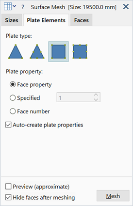
Plate type
Type of plate to generate. Possible options are Tri3, Tri6, Quad4 and Quad8. When selecting Quad elements, the mesh will contain predominantly those element types, however, Tri elements may still be generated where necessary to complete the surface mesh.
Selecting higher order elements will maintain the geometry curvature.
Plate property
Property type for generated plate elements.
-
Face property
Plate elements inherit the property type assigned to geometry faces.
-
Specified
All plate elements are assigned the specified property type.
-
Face number
Plate elements are assigned a property type based on the face number.
Auto-create properties
If set, a new property set is automatically created whenever a generated plate element is assigned a new property number.
Dialog - Faces Tab
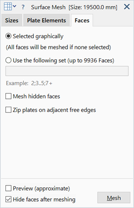
Face selection
Specifies which faces to mesh.
-
Selected graphically
Selected faces will be meshed.
If no faces are selected, then all faces will be meshed.
-
Use the following set
Meshes only specified faces. These can be specified as integers in a comma separated list.
Each entry in the list may be a single number or a range. Two types of ranges are possible:
- Bounded - All entity sets between two numbers, inclusive of the bounds (e.g., 3..6)
- Unbounded - All entity sets larger than or equal to the given number (e.g., 10+).
An example list is 2, 3, 4..6, 10+.
Mesh hidden faces
If set, all candidate faces in the model (based on the selection setting above) will be meshed, even if they are hidden.
If not set, only visible candidate faces will be meshed.
Zip plates on adjacent free edges
Plate element edges generated on common geometry edges are always zipped in the meshing procedure, so this option applies only to plate element edges on disconnected geometry edges that are geometrically within the model zip tolerance.
If set, such plate edges are zipped for nodes within the zip tolerance.
If not set, such plate edges are not zipped.
Dialog - Common
Preview
Indicates an approximate mesh size on the model by drawing the approximate location of nodes along face edges
Hide faces after meshing
If set, the geometry will be hidden after meshing.
See Also