Tools: Project to Line
Description
This projection method is used by Copy Tools: by Projection to Line, Move Tools: by Projection to Line and Extrude Tools: by Projection to Line.
The operation projects the source node to the target line. The validity of the extruded entity produced depends on the source entity and its shape, as well as the projection direction.
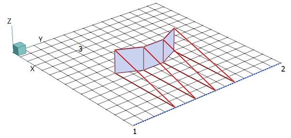
In the following images, the three plate elements are the source and they are projected to the target (blue) line between nodes 1 and 2. In each image the projection result is indicated by the red lines, which trace the projection path of the source nodes.
Projection Direction - Target Normal
This projection method projects source nodes directly onto, and perpendicular to, the target line.
For an extrusion operation, the source plates below would produce wedge brick elements. For a copy or move operation, they would produce plate elements collapsed onto a line (i.e., invalid plates).
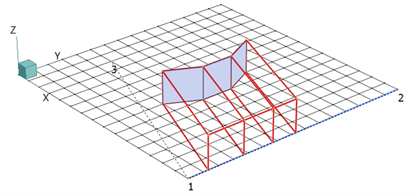
Projection Direction - Parallel
This projection method requires the definition of a projection direction by the selection of two points. In the figure below, these points are nodes 3 and 1 (the projection direction is the dashed line). Each source node is projected towards the target line in a direction parallel to the dashed line. If the projection intersects the target line, the projection stops there. If the projection does not intersect the target line, the projection stops when it intersects the plane whose normal is given by the line perpendicular to the target line and passing through the first point on the projection direction line (i.e., node 3). This means that the projection direction does not have to intersect the target line.
For an extrusion operation, the source plates below would produce hexahedral brick elements with edges parallel to the projection direction. For a copy or a move operation, they would produce plate elements on the projection plane.
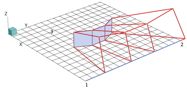
Projection Direction - Conical
This projection method requires the definition of a cone apex point from which a projection direction is defined for each source point. Once defined, this direction (one per source point) is used in the same way as the dashed line is used in the parallel projection method. The result is a conical projection that stops either on the target line or on a target plane defined for each source point.
In the figure below, the apex is at node 3. For an extrusion operation, the source plates below would produce hexahedral brick elements. For a copy or a move operation, they would produce plate elements on the projection planes.
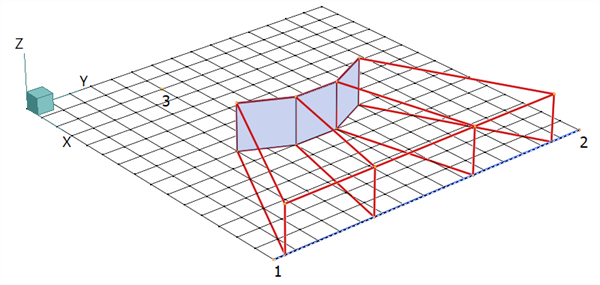
Projection Direction - Source (Plate) Normal
This projection method is a further extension of the parallel method whereby a projection direction is defined for each source point based on the average normal of the connected plates at that point. Once defined, this direction (one per source point) is used in the same way as the dashed line is used in the parallel projection method. The result is a projection that stops either on the target line or on a target plane defined for each source point.
For an extrusion operation, the source plates below would produce hexahedral brick elements. For a copy or a move operation, they would produce plate elements on the projection planes.
Note that no projection is produced if this method is applied to nodes that are not connected to plate elements.
Equi-space on Line
If this option is set, the set of nodes projected to the line are spaced uniformly along the line after they are projected.

See Also