Tools: Project to Plane
Description
This projection method is used by Copy Tools: by Projection to Plane, Move Tools: by Projection to Plane and Extrude Tools: by Projection to Plane.
The operation projects the source node to the target plane.
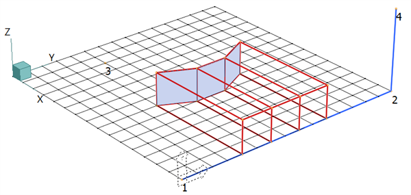
In the following images, the three plate elements are the source and they are projected to the target plane defined by nodes 1, 2 and 4. In each image the projection result is indicated by the red lines, which trace the projection path of the source nodes.
Projection Direction - Target Normal
This projection method projects source nodes directly onto, and perpendicular to, the target plane.
For an extrusion operation, the source plates below would produce hexahedral brick elements with edges perpendicular to the projection plane. For a copy or move operation, they would produce plate elements on the projection plane.
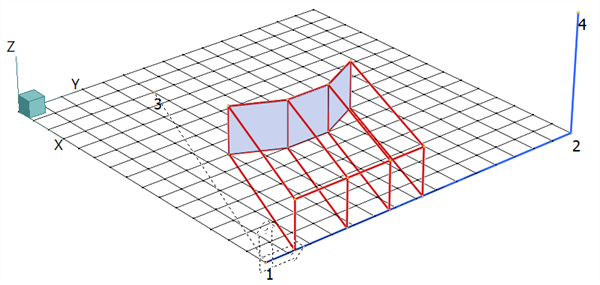
Projection Direction - Parallel
This projection method requires the definition of a projection direction, which in the figure below is given by the (dashed) line from node 3 to node 1. Each source node is projected towards the target plane in a direction parallel to the dashed line.
For an extrusion operation, the source plates below would produce hexahedral brick elements with edges parallel to the projection direction. For a copy or move operation, they would produce plate elements on the projection plane.
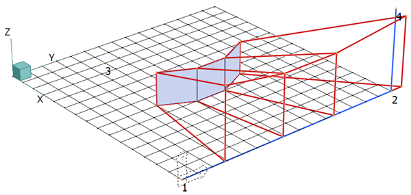
Projection Direction - Conical
This projection method requires the definition of a cone apex point from which a projection direction is defined for each source point. Once defined, this projection direction (one per source point) is used in the same way as the dashed line is used in the parallel projection method. The result is a conical projection onto the target plane for each source point.
In the figure below, the apex point is node 3. For an extrusion operation, the source plates below would produce hexahedral brick elements. For a copy or a move operation, they would produce plate elements on the projection plane.
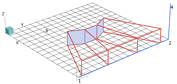
Projection Direction - Source (Plate) Normal
This projection method is a further extension of the parallel method whereby a projection direction is defined for each source point based on the average normal of the connected plates at that point. Once defined, this direction (one per source point) is used in the same way as the dashed line is used in the parallel projection method.
For an extrusion operation, the source plates below would produce hexahedral brick elements. For a copy or move operation, they would produce plate elements on the projection plane.
Note that no projection is produced if this method is applied to nodes that are not connected to plate elements.
See Also