Export: IGES File

Description
Exports geometry faces in a Strand7 model to the IGES (Initial Graphics Exchange Specification) format.
Note that finite element data is not exported.
As the IGES standard offers different formats of data representation, a number of export options are available to specify the particular format to be used. Interpretation of the IGES data may vary across different CAD systems; by appropriately adjusting the export options, the success rate of transferring geometry data from Strand7 to other systems can be increased. A number of pre-set options are available for some of the more popular CAD and modelling systems such as Inventor, Rhino and SolidWorks.
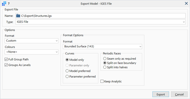
Dialog
Name
Opens the file dialog to specify the location and name of the file to be exported.
Export Format
Data format of the exported IGES file.
-
Default
A standard set of options regarded as best overall, without reference to a specific CAD system.
-
Strand7
Pre-set options best suited for Strand7.
-
Inventor
Pre-set options best suited for Inventor.
-
Rhino
Pre-set options best suited for Rhino.
-
Solidworks
Pre-set options best suited for SolidWorks.
-
IGES 143
Bounded Surface (143) representation.
-
IGES 144
Trimmed Parametric Surface (144) representation.
-
IGES 186
Manifold Solid B-rep (186) representation.
-
IGES 514
Open Shell (514 form 2) representation.
-
Custom
Options to be set manually.
Colours
Colour options for the exporting faces.
-
None
Colours are not assigned to IGES faces.
-
Face Colour
Face colours are assigned to IGES faces.
-
Group Colour
Group colours are assigned to IGES faces.
-
Property Colour
Property colours are assigned to IGES faces.
Full Group Path
If set, the full group path will be used as the IGES level name.
Groups As Levels
If set, Strand7 group definitions will be exported as IGES levels.
Format Options
Advanced options available when the Export Format is set to Custom.
Format
-
Bounded Surface (143)
A bounded surface entity is used to define a face.
-
Trimmed Parametric Surface (144)
A trimmed parametric surface entity is used to define a face.
-
Open Shell (514 form 2)
An open shell entity is used to define a face.
-
Manifold Solid B-rep (186)
Manifold solid B-rep entity is used to define a face.
Curves
-
Model only
Only Model curves are exported. All parameter curve entity pointers will be set to zero.
-
Parameter only
Only parameter curves are exported. All model curve entity pointers will be set to zero.
-
Model preferred
Both model and parameter curves are exported with the model curves marked as the preferred curves.
-
Parameter preferred
Both model and parameter curves are exported with the parameter curves marked as the preferred curves.
Periodic Faces
-
Seam only as required
A seam is placed along the boundary of periodic faces that have two outer loops.
This is necessary because IGES does not allow for more than one outer loop per face.
-
Split on face boundary
A seam is placed along the boundary of all periodic faces so that parametric loops do not extend outside the default parametric range of a periodic surface.
-
Split into halves
Two seams are placed on all periodic faces, one seam along the boundary and one through the centre parallel to the boundary.
This prevents the face boundary extents from overlapping.
Keep Analytic
If set, analytic surfaces (planes, cones, spheres and tori) are exported using analytic surface definitions.
If not set, analytic surfaces are converted to, and exported as, B-spline surfaces.
Note that faces with analytic surfaces are exported with model (i.e., 3D) trimming curves only. If the format has the provision of parameter curves (i.e., 2D) or if parameter curves have been specified for export then these faces are exported with model curves only.
See Also