Extrude Tools: by Line

Description
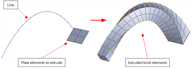
Extrudes selected nodes, beams, plates and brick faces along a line defined by a series of connected beam elements.
Nodes are extruded into beams or links, beams are extruded into plates, and plates and brick faces are extruded into bricks.
Dialog
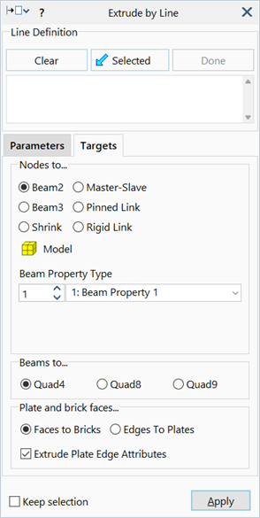
Line Definition
A list of beam element numbers that defines the extrusion line.
The list must contain an open ended series of beam elements connected end-to-end; that is, the two ends of the line must be free ends.
Beam element numbers can be manually entered, pasted from the clipboard or assigned based on currently selected entities. When the line definition list is highlighted, the hot pointer is available to click and select beam elements from the model window. The order of the beam elements in the list is not important. If the list contains duplicates, these are automatically removed when the tool is executed.
Clear
Clears the line definition list.
Assign Selected
Assigns currently selected beam elements to the line definition list.
Done
Exits the hot pointer selection mode.
Divisions
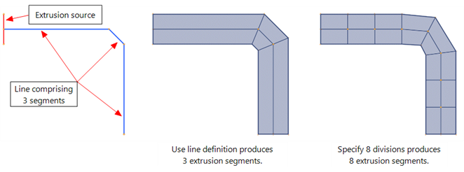
The number of divisions used for the extrusion along the full length of the line. Two options are available:
-
Specify
The extrusion comprises the specified number of equal length extrusion segments, irrespective of how many beam elements have been used to define the line, or the individual lengths of those elements. Effectively, the line definition is re-sampled with the specified number of equal length straight segments over the original line definition.
-
Use line definition
Generates an extrusion segment for each beam element that defines the line.
Direction
This option determines at which end the extrusion starts. Two options are available:
-
Auto
The end of the extrusion line is automatically selected as the end nearer to the entities to be extruded.
-
Reverse
The end of the extrusion line is selected as the other end relative to the Auto option.
Axial rotation (deg)
The basic function of this tool is the extrusion of source elements parallel to an arbitrarily defined line. To impart a twist to the extrusion, applied uniformly from the start to the end of the line, enter a non-zero axial rotation angle. This is the total angular twist from start to end. The angle is positive according to the right hand rule in the direction of extrusion.
Radial scale
In addition to a twist angle, the extruded source can also be scaled radially to taper the extrusion between the ends. A radial scale greater than 1.0 produces an expanding taper, whereas a radial scale less than 1.0 produces a contracting taper.
Common Controls
- Property Increment
- Extrude Plate Edge Attributes
- Source
- Nodes to...
- Beams to...
- Plates and brick faces...
- Keep Selection
See Also