Utility: Make BXS

Description
Calculates section properties and generates beam cross section geometry from a 2D plate mesh positioned on the XY plane.
The cross section geometry and the calculated section properties can be saved to a BXS file. The BXS file can be imported to any beam property set of any model for visualisation, analysis and result presentation. The BXS file is units-aware. See File Formats: BXS File.

Dialog
Save section
Saves the cross section geometry and properties to a BXS file. See File Formats: BXS File.
Print preview
Opens the print preview page.
See Print Preview: Printing Layouts.
Copy graphic to clipboard
Copies the cross section geometry as in image to the Windows clipboard.
Copy properties to clipboard
Copies the section properties to the Windows clipboard.
Shear stress 1
Displays the contour pattern of shear stress due to a shear force in the principal 1 direction.
Shear stress 2
Displays the contour pattern of shear stress due to a shear force in the principal 2 direction.
Torque stress
Displays the contour pattern of shear stress due to torque.
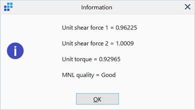
Check integration of unit shear force and torque
Computes the shear forces and torque recovered from direct integration of the shear stresses due to unit applied shear forces and torque.
Values close to one indicate a good quality section for nonlinear material (MNL) analysis. The MNL quality of the section can be improved by increasing the source plate mesh density, at the expense of longer solver running time.

Cross section fill / outline colour
Opens the colour selection dialog for selection and assignment of a colour to the cross section.
Display options
Show/hide options for components in the cross section graphic.
Cross section graphic
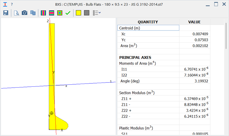
The cross section geometry is displayed with its centroid, shear centre, local and principal axes. Local axes are axes parallel to the global axes but located at the centroid of the section. Global axes are the axes in which the source plate mesh is defined.
-
Local Axes
Local x, y axes of the cross section positioned at the centroid of the section.
-
Principal Axes
Principal 1, 2 axes of the cross section. The axes cross over at the centroid of the section.
-
Global Axes
The X, Y axes at the model origin.
-
Shear Centre
The circle with cross hair positioned at the shear centre of the section.
-
Outline
Trace lines of the section.
Section properties
A list of section properties corresponding to the cross section geometry.
-
QUANTITY
The section property type.
The list includes centroid, area, moments of area in local, global and principal axes, principal axis angle, radii of gyration, section and plastic moduli in both local and principal axes, shear centre offsets, shear areas, radius area integral, torsion constant and warping constant.
-
VALUE
The values of section properties.
Notes
- The source plate mesh representing the cross section geometry must be in the XY plane.
- Free plate edges (Detect: Plate Edges) within the cross section geometry represent internal cracks. Free edges within the geometry should be removed if internal cracks are not intended.
- The calculated cross section properties are not dependent on material properties.
- Links can be used to join multiple parts together into composite sections of the same material.
See Also