Entities: Links
Description
Links provide a straightforward mechanism for defining specific relationships between degrees of freedom at nodes in a model. These relationships are implemented as multi-point constraint equations in the Strand7 solvers.
Although Strand7 offers the possibility of defining these multi-point constraint equations directly, for the most common situations Strand7 offers a selection of Links that generate the equations automatically.
Links are similar to elements in that they are defined by connecting them between nodes. Unlike elements, they do not reference material data, but instead they are classified by type - each type represents a different physical situation between nodes (for example, a Rigid Link represents an infinitely rigid connection between two or more nodes).
The following describes the available link types.
Master-Slave

The Master-Slave link defines a direct relationship between the degrees of freedom of two nodes.
For example, two nodes can be forced to produce the same DX displacement by connecting a Master-Slave link between them with the DX degree of freedom set.
The terms master and slave are not intended to differentiate one end of the link from the other, but simply enable a general description about the behaviour of the link; the behaviour will be identical irrespective of the order in which the nodes in the link are defined. Such links can therefore be viewed as forcing two degrees of freedom to work together in carrying a load, rather than forcing the slave to have the same displacements as the master. The following example illustrates this.
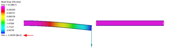
Two cantilever beams are modelled. The beam on the left is carrying a load, whereas the beam on the right is unloaded. The load on the loaded cantilever produces a displacement of -2.36 mm. The unloaded cantilever show no displacement.
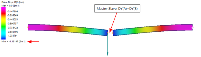
If a Master-Slave link is attached to constrain DY at both ends to be the same, without any other changes, we now see that the two beams deflect by the same amount, and that this amount is now half the amount by which the single beam deflected.
Any or all of the degrees of freedom at nodes may be constrained. The degrees of freedom may be referenced in any UCS. For example, in a Cartesian system, each of DX, DY, DZ, RX, RY and RZ may be constrained, whereas in a cylindrical coordinate system, each of DR, DT, DZ, RR, RT and RZ may be constrained.
The Negate flag, if set, enforces the displacements of the two nodes to have the same magnitude but opposite signs.
When used in the Steady Heat or Transient Heat solvers, a Master-Slave link enforces the same temperature at two nodes connected by the link as long as the DX option is set. The Negate option is ignored by the heat solvers.
Sector-Symmetry
The Sector-Symmetry link is used to enforce a cyclic symmetric behaviour when only one sector of a complete circular structure is modelled. The cyclic symmetry approach is valid in static analysis when the loads on one sector are repeated on all sectors. In dynamic analysis the approach is valid for dynamic response that repeats on every sector.
The origin of the rotational axis of the modelled sector must be located at the origin of the global XYZ system and have its rotational axis parallel to one of the global X, Y or Z axes.
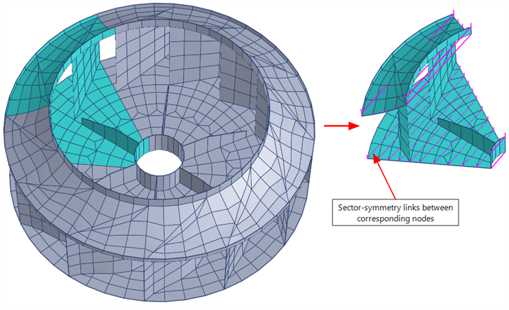
A typical structure with cyclic symmetry is an impeller such as that shown below. The impeller consists of six repeating 60-degree sectors. The modelled sector is constrained with the Sector-Symmetry links between the symmetry planes.
If the nodes on one side of the sector boundary are different to the nodes on the other side of the sector boundary, attachment links can be used to bridge the misalignment. See Insert Link Clusters: Sector-Symmetry.
When used in the Steady Heat or Transient Heat solvers, a Sector-Symmetry link enforces the same temperature at the nodes connected by the link.
Coupling
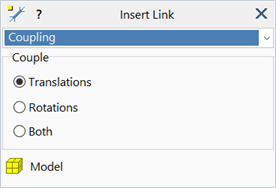
The Coupling link is used to couple the displacement components of one node to two other nodes. The displacements of the coupled node are assigned a weighted average of the displacements of the other nodes, based on the relative positions of the three nodes.
If Translations is set, only the translational degrees of freedom are averaged. If Rotations is set, only the rotational degrees of freedom are averaged. If Both is set, both the rotational and translational degrees of freedom are averaged independently.
The same outcome can be achieved by superimposing two separate coupling links, one for the translations and another for the rotations.
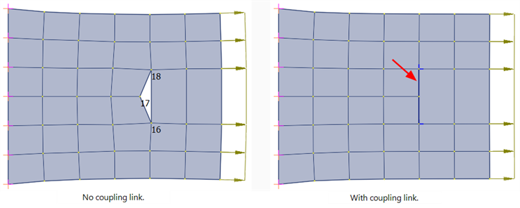
A typical use of the Coupling link is to enforce compatibility between disconnected elements. An example is shown below where node 17 is coupled to nodes 16 and 18 to establish a compatible connection.
When used in the Steady Heat or Transient Heat solvers, the coupling link enforces the middle node to have a temperature that is the weighted average of the other two nodes, irrespective of the selected coupling option.
Pinned
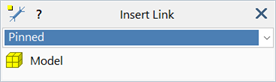
The Pinned link provides an infinitely stiff pinned connection between two nodes. It acts just like an infinitely stiff bar or truss element connected between two nodes.
The link is rigid only in its axial direction and does not impose any constraint on the nodal rotations.
This link is normally used in preference to truss elements with large axial stiffness because it produces the desired effect without the need to insert an excessively large local stiffness into the global stiffness matrix.
When used in the Steady Heat or Transient Heat solvers, a Pinned link enforces the same temperature at the two nodes connected by the link.
Rigid
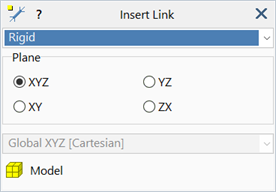
A Rigid link acts just like an infinitely stiff beam element connected between two nodes. The link can be rigid in 3D space (providing rigidity in all degrees of freedom), or rigid only on a plane identified by the selection of a Cartesian UCS (providing rigidity only on a plane without constraining out-of-plane translation or rotation).
A typical example of the use of a Rigid link on a plane is the modelling of rigid diaphragms for the analysis of floor slabs. If a floor slab lying in the XY plane can be assumed to be infinitely rigid against in-plane loads, rigid links in the XY plane can be applied between the nodes to enforce this condition.
When used in the Steady Heat or Transient Heat solvers, a Rigid link enforces the same temperature at the two nodes connected by the link.
Shrink
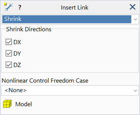
The Shrink link ensures that the sum of the displacements in the set directions at two nodes equals zero.
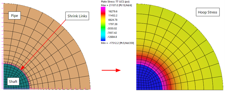
This link is typically used to model shrink fits or interference fits. In the image below, the interference fit between a shaft and a pipe is modelled as a 2D quarter model, plane strain analysis. The shaft is oversize compared with the hole in the pipe, and the overlap in the nodes connects a series of shrink links. The result shows the expected hoop stress distribution; the shaft is under a state of hydrostatic compression, and the pipe experiences tensile hoop stress at the inner surface.
In nonlinear analyses, a load factor must be assigned to the selected Nonlinear Control Freedom Case to activate the shrink displacement. A load factor of 0.0 produces no shrink displacement and a load factor of 1.0 produces the full shrink.
The Steady Heat and Transient Heat solvers ignore Shrink links.
2-Point
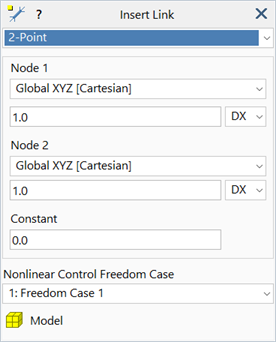
Using the 2-Point link, a general constraint can be defined in the following form:

where
 ,
,  and
and  are user-defined constants, and
 and
and  are two displacement components with
  and
and  being the node numbers and
  and
and  the displacement component indexes in the selected coordinate systems.
Note that
 and
and  can be the same node when
  and
and  are different degrees of freedom (i.e., the equation can constrain two degrees of freedom at the same node).
When used in the heat solver with  , the 2-Point link enforces the relationship between temperature
  at the two nodes
  and
and  .
.
Attachment
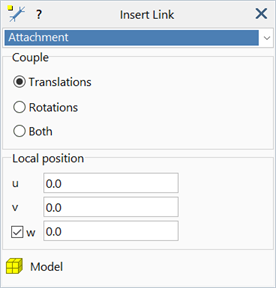
An Attachment link enforces the displacements and/or rotations at the node, to be interpolated according to the shape functions of the element to which the link is attached. The element shape functions are evaluated at a prescribed position on the element.
The link is mainly used to connect incompatible meshes. It can link a node to any location on a target element, inluding:
- along a beam element,
- on the surface of a plate element,
- on the face of a brick element, or
- inside a brick element.
The connection between the degrees of freedom can be for displacements only, for rotations only, or for both displacements and rotations.
Each Attachment link generates a multi-point constraint equation, automatically assigning the coefficients based on the element to which the node is connected. The target element provides the coefficients by evaluating its shape functions at the target location.
For example, if the end of a truss element connects to the centre of a 4-node plate element, an attachment link would enforce the following conditions between the movement of the node on the truss element and the nodes on the plate element:

where
 are the displacements in the local system of the plate element.
The coefficients (0.25 in the above equation), will be different for the truss end located at a different position on the plate element.
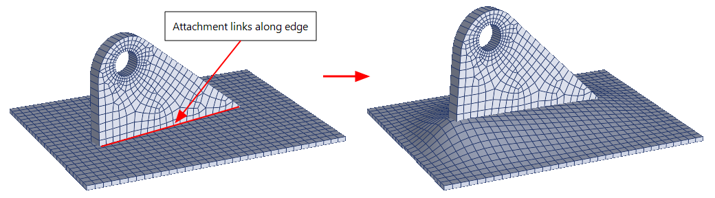
In the following image, attachment links have been automatically inserted between the plate and the lug to weld the two parts together. The plate and the lug do not share nodes.
User-defined MPL
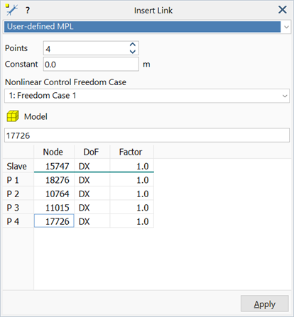
The User-defined Multi-point link (MPL) is used to couple displacement components at a node with displacement components at any number of other nodes via a linear constraint equation. The displacement components can be defined in the global coordinate system or in a UCS.
The constraint equation for a Multi-point link can be expressed as

where
 ,
,  ,
,  ,
,  ,
,  are constants,
 ,
,  ,
,  ,
,  are nodes,
and
are nodes,
and
 ,
,  ,
,  ,
,  are components or degrees of freedom.
That is,
 ,
,  ,
,  ,
,  are displacement of component
  ,
,  ,
,  ,
,  of nodes
  ,
,  ,
,  ,
,  .
.
 ,
,  ,
,  ,
,  may refer to components in different coordinate systems.
When the displacement components are either all translations or all rotations,  ,
,  ,
,  ,
,  ,
,  will be non-dimensional whilst
  will have the units of the selected displacement components (length or degree/radian). Otherwise, their dimensionality will depend on the constrained degrees of freedom for the whole equation.
In nonlinear analysis,  can be scaled by factors applied to the selected Nonlinear Control Freedom Case.
All other link types could be developed using the general multi-point link, at least for linear analysis, although this would not be as efficient as using the specific link types directly.
Interpolated MPL
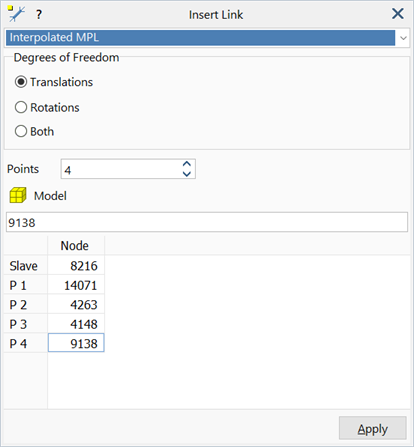
The Interpolated Multi-point link (MPL) is mainly used to distribute mass or load to multiple nodes without influencing the stiffness of the structure. Essentially it couples multiple nodes to a single slave node without linking them all to each other. Attributes applied to the single slave node are distributed to the master nodes. This is useful as a way to smear a mass onto a group of nodes or to apply load to many locations from a single point.
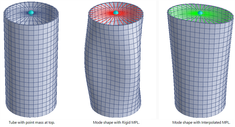
In the example illustrated below, a point mass is attached to the unrestrained end of a tube, firstly using a Rigid MPL and secondly using an Interpolated MPL. The Rigid MPL does not allow the end of the tube to deform. The Interpolated MPL does not restrain the deformation at the end of the tube.
Master-Slave MPL
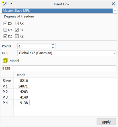
The Master-Slave Multi-point link (MPL) is equivalent to a cluster of individual Master-Slave links each connected from the slave node to a different master node. However, as it is a single link, not multiple links, it is generally more efficient to work with an MPL than with a cluster of individual links.
Pinned MPL
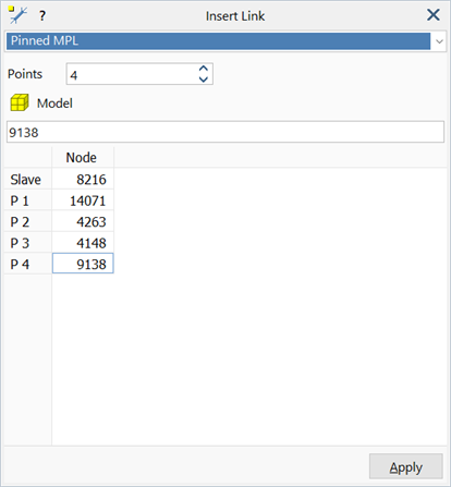
The Pinned Multi-point link (MPL) is equivalent to a cluster of individual pinned links each connected from the slave node to a different master node. However, as it is a single link, not multiple links, it is generally more efficient to work with an MPL than with a cluster of individual links.
Rigid MPL
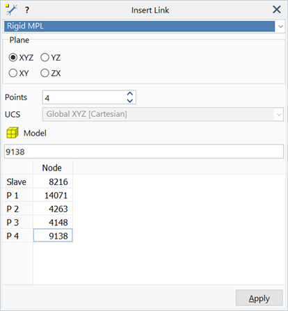
The Rigid Multi-point link (MPL) is equivalent to a cluster of individual Rigid links each connected from the slave node to a different master node. However, as it is a single link, not multiple links, it is generally more efficient to work with an MPL than with a cluster of individual links.
Reaction MPL
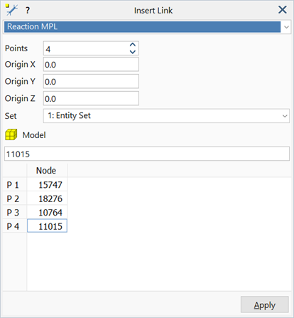
The Reaction Multi-point link (MPL) is a special type of link that does not enforce any constraint relationship between nodes or degrees of freedom. Instead, the link is used to calculate force and moment resultants anywhere in the model. It sums the element nodal forces and moments (or flux for heat transfer analysis) at selected nodes of selected elements. This enables the extraction of results such as in-plane shear in a lift core at each floor, the bending moment diagram of the lift core and the summation of heat flux/forces/moments about any point in space, to name a few. A free body diagram of any part of a structure can be produced using these links.
The nodes are selected explicitly by attaching them to the MPL itself, similarly to the way any other MPL is defined. The elements are selected by referencing an entity set (Global: Entity Sets).
The link provides the flexibility to calculate resultants anywhere in the model.
See Also