Insert Link Clusters: Sector-Symmetry
Description
Inserts sector-symmetry links between pairs of nodes on two radial planes to enforce a cyclic symmetry constraint between those planes.
The symmetry axis is selected as one of the global XYZ axes, and a polar coordinate system,  , is implicitly defined based on the choice of axis, centered at the origin. The
  (angular) positions of the two planes, (plane 1 and plane 2) are defined with reference to this polar coordinate system. The entire mesh, that is, the sector, must be defined such that all nodes have angular positions between the two planes.
Sector-symmetry links are automatically inserted between the nodes on plane 1 and their corresponding nodes on plane 2. Two nodes are corresponding when a node on plane 1 has the same  and
and  coordinates as a node on plane 2.
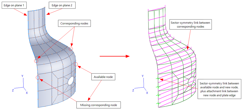
Ideally, every node on plane 1 will have a corresponding node on plane 2, in which case a sector-symmetry link is directly inserted between every pair of corresponding nodes to fully define the cyclic symmetry of the sector. In the case where a node on plane 1 does not have a corresponding node on plane 2, a new node is automatically inserted on plane 2, with  and
and  coordinates matching those of the node on plane 1; the sector-symmetry link is then attached between the node on plane 1 and the newly created node on plane 2. The new node on plane 2 is then attached to the nearest element on plane 2 by inserting a new attachment link (Insert: Attachment Link). The same procedure is used to attach nodes on plane 2 that have no corresponding node on plane 1.
The following image illustrates these two situations for a 60 degree sector of a shell mesh.
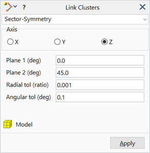
Dialog
Axis (X/Y/Z)
Axis of rotation about which the symmetry conditions are defined.
Must be one of the global axes passing through the origin.
Plane 1 (deg)
Angle defining the angular position of the first plane.
The angle value can be manually entered or retrieved from the model window by clicking a node.
Plane 2 (deg)
Angle defining the angular position of the second plane.
The angle value can be manually entered or retrieved from the model window by clicking a node.
Radial tol (ratio)
The radius of a node on a plane multiplied by the Radial tol (ratio) produces a distance tolerance. A node on plane 1 is deemed to have a corresponding node on plane 2 if the  and
and  coordinates of the two nodes are within this distance tolerance. To pair up corresponding nodes, the function will search for the best matching pair of nodes, not necessarily the first matching pair.
Angular tol (deg)
The maximum angular difference between a node and a specified plane, for the node to be considered to lie on that plane.
Target group
The group to which the inserted link clusters are added. See Target group.
See Also