LAYOUTS: Cavities
Description
Defines cavity data that can be used to fill a closed cavity bounded by plate elements and/or brick faces.
Typical applications of cavity data includes the modelling of the pressure effects of fluid inside closed volumes such as the inside surface of a balloon membrane, or the gas inside an IGU (Insulated Glass Unit).
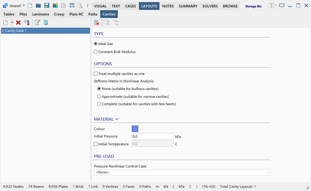
The LAYOUTS: Cavities sub-tab is divided into two panes: cavity data list on the left, and cavity data on the right.
Cavity Data List
Situated on the left of the window, it lists the available cavity layouts.
Data Pane
Situated on the right of the window, it displays the parameters of the current cavity data.
TYPE
Cavities can represent two types of fluid:
-
Idea Gas
The cavity enforces the ideal gas relationship between pressure, volume and (optionally) temperature.
-
Constant Bulk Modulus
The cavity is filled with a fluid that enforces a constant relationship between pressure and volumetric strain, by the definition of a constant bulk modulus.
For nonlinear analysis, the following option is available:
-
Treat multiple cavities as one
If set, multiple volumes that reference the same cavity layout are assumed to be connected so that they have the same internal pressure during the analysis.
If not set, multiple volumes can still reference the same cavity layout, but they are assumed to be independent in terms of their internal pressure.
-
Stiffness Matrix in Nonlinear Analysis
This option selects the numerical approach used to solve nonlinear cavity problems. The option is used only to help improve the convergence of different types of cavities. For a converged analysis, all three options will produce the same results, within some numerical tolerance.
If None is selected, the cavity stiffness matrix is not added to the global stiffness matrix. The change in cavity pressure due to changing volume during the iterations is accounted for by monitoring the cavity volume and applying the corresponding pressure to the relevant nodes. For large bulbous cavities, this option is usually the most efficient. It will typically require more iterations than the other options, but the per-iteration time is shorter.
If Approximate is selected, the cavity stiffness matrix is approximated via the stiffness of a cluster of tetrahedral elements automatically generated within the cavity. This stiffness matrix will not be the true tangent stiffness for the cavity, but its bandwidth will be significantly smaller than for the Complete option. The purpose of the approximate stiffness matrix is to avoid numerical oscillation that can occur when the cavity stiffness matrix is not included (i.e., when using the None option). The Approximate method is usually the best one for the analysis of narrow cavities whose volume may be sensitive to small displacement changes that can cause numerical oscillation and/or convergence difficulties.
If Complete is selected, the full (or "exact") tangent stiffness matrix for the cavity is added to the global stiffness matrix. This cavity stiffness matrix is assembled via the classical integration procedure used for the assembly of displacement based finite elements. This method will require fewer iterations than the other methods. However, for large cavities (i.e., those that connect a large number of nodes) the method will produce a very large bandwidth in the global stiffness matrix, which can significantly increase the per-iteration time. The Complete method is usually best for very small cavities (i.e., those consisting of a small number of nodes).
Toolbar Functions
Ideal Gas Parameters
MATERIAL
Specifies the initial conditions of the gas cavity defined by internal pressure  , volume
  and temperature
  . That is,

where subscript 1 refers to initial conditions and subscript 2 refers to cavity condition during simulation.
The initial volume  is automatically determined upon assigning the cavity data to a closed volume by applying it as an attribute to a collection of plate elements and/or brick faces.
Colour
Selects the display colour of the cavity data in the model; it is used for drawing the attribute on elements in the model window.
Initial Pressure
The initial absolute pressure of the gas cavity  .
.
Cavity pressure is always positive with zero pressure representing a vacuum. In post-processing, cavity pressure is reported as a normal stress on the surfaces where a cavity layout is applied. As this is considered a stress, it uses the standard sign convention for stress (i.e., compressive stress is negative and tensile stress is positive). Therefore, internal cavity stress in post-processing will appear as a negative stress on the surfaces of elements on which a cavity layout is defined.
Initial Temperature
The initial temperature of the gas cavity  . This temperature is automatically converted to absolute temperature for cavity calculations.
PRE-LOAD
Pressure Nonlinear Control Case
Specifies a load case that scales the initial pressure of the gas cavity  up or down during a simulation according to the load factors that are assigned to the load case.
This function is available in SOLVERS: Nonlinear Static Settings, SOLVERS: Quasi-static Settings, SOLVERS: Linear Transient Dynamic Settings, SOLVERS: Nonlinear Transient Dynamic Settings. If a controlling load case is not assigned, is not active or the load factor becomes zero, the cavity is excluded from the analysis.
Constant Bulk Modulus Parameters
MATERIAL
Specifies the material data of the fluid in the cavity.
Colour
Selects the display colour of the cavity data in the model; it is used for drawing the attribute on elements in the model window.
Bulk Modulus
Bulk modulus of the material, which relates volumetric strain to applied uniform pressure.
Thermal Expansion
Coefficient of linear thermal expansion.
Note that the linear and volumetric thermal coefficients are different quantities. The volumetric coefficient is three times the linear coefficient.
PRE-LOAD
Lists all available load cases in the model enabling the application of pre-load, either as pre-stress or as pre-strain, to the cavity in those load cases. Pre-load in the cavity can then be scaled by assigning load factors to the respective load cases.
A positive value of pre-load causes an unrestrained cavity to contract.
A negative value of pre-load causes the unrestrained cavity to expand.
See Also