SOLVERS Parameters: Iteration (Structural)
Description
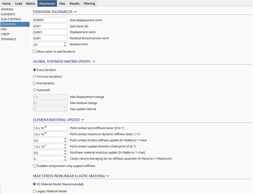
Sets the iteration parameters that control the execution and convergence of the Nonlinear Static, Quasi-static and Nonlinear Transient Dynamic solvers.
ITERATION TOLERANCES
For these solvers, a load step or time step is regarded as converged when both the Displacement norm and Residual force/moment norm iteration tolerances are satisfied. The Zero displacement and Zero force parameters are used in place of these criteria in specific situations.
Displacement norm
This parameter is used to assess whether the displacements have converged. Displacements are considered converged at the end of an iteration when the norm of the iterative displacements divided by the norm of the total displacements is less than the specified value. That is, when

where
 = current total displacement vector,
 = current displacement iteration vector,
 = norm of a vector, and
 is the Displacement norm.
Residual force/moment norm
This parameter is used to assess whether the internal forces balance the external loads. These are considered as balanced when the norm of the residual force vector divided by the norm of the applied loads is less than the specified value. That is, when

where
 = nodal force vector due to all currently applied external load,
 = current residual force vector,
 = norm of a vector, and
 is the Residual force/moment norm.
Zero displacement
If the total displacements are very close to zero, it can be difficult to calculate the Displacement norm because the denominator of the term approaches zero. At the same time, as the solution converges, the iterative displacements themselves approach zero (i.e., the numerator also approaches zero). This produces a case of near zero divided by near zero, and therefore the Displacement norm is not reliable.
An example where the displacements are very close to zero is the case where loads are removed and the structure returns to its original position. Due to numerical round-off, it will generally not return to exactly zero as there will always be some small numerical residuals.
To deal with this situation, the Zero displacement parameter is used, defined in the length units of the model. If at the end of an iteration the maximum iterative displacement at any node is less than this length, the Displacement norm is assumed to have been satisfied.
The Zero displacement parameter is set as 10-8 m by default (the equivalent length is used when the model is defined in other length units). By setting this value to zero, this check is effectively skipped.
Zero force
If the applied load is zero due to unloading, or near zero due to numerical round-off in the transformation operations, the Residual force/moment norm is difficult to calculate because the denominator is zero or near zero. As the solution approaches convergence, the residual forces generated also approach zero, and this produces the case of near zero divided by near zero, and therefore the Residual force/moment norm is not reliable.
To deal with this situation, the Zero force parameter is used, defined in the force units of the model. If at the end of an iteration the maximum residual force at any node is less than this force, the Residual force/moment norm is assumed to have been satisfied.
The Zero force parameter is set as 10-3 N by default (the equivalent force is used when the model is defined in other force units). By setting this value to zero, this check is effectively skipped.
Iteration limit
This parameter specifies the maximum number of iterations allowed in each step/sub-step for convergence. In cases where the default value is not sufficient to achieve convergence, techniques such as automatic sub-stepping may be applied, in addition to increasing the iteration limit.
Allow solver to add iterations
If set, the solver will continue iterating if convergence has not been achieved within the Iteration limit, provided that the Residual force/moment norm and Displacement norm are still reducing (i.e., the iterations continue while the solution remains convergent).
GLOBAL STIFFNESS MATRIX UPDATE
Every iteration
If this option is selected the stiffness matrix is formed at every iteration. This increases the solving time because the global matrix needs to be factorised at every iteration, but usually improves the rate of convergence of the solution.
First two iterations
If this option is selected the stiffness matrix is formed only at the first and second iterations of a load step or sub-step. The stiffness matrix formed at the second iteration will be used for the remainder of the iterations for the load step or sub-step. The solution time for each iteration after the second one is much shorter, but the solution will usually require more iterations than when updating at every iteration.
First iteration
If this option is selected the stiffness matrix is formed only at the first iteration of each load step or sub step. The stiffness matrix formed will be used for the remainder of the iterations for the load step or sub-step. The solution time for each iteration after the first iteration is much shorter, but the solution will usually require more iterations than when updating at every iteration.
Automatic
If automatic is selected the global stiffness matrix is updated according to the following rules:
-
Max displacement change
This parameter is used to activate a matrix update while the Displacement norm is greater than the Max displacement change.
-
Max residual change
This parameter is used to activate a matrix update while the Residual force/moment norm is greater than the Max residual change.
-
Max update interval
This parameter is used to activate a stiffness matrix update at least every Max update interval iterations.
ELEMENT/MATERIAL UPDATE
Point contact zero stiffness factor (0 to 1)
When a point contact element is inactive in a nonlinear analysis, its stiffness is scaled by this factor. The default value is 10-6. Although a value of zero can be used in many problems involving contact, in practice a small stiffness is used to provide better numerical stability. The value used does not have a significant effect to the results of a converged step, only its convergence rate.
Point contact maximum dynamic stiffness factor (>1)
The stiffness of a dynamic stiffness point contact element can be increased during the iterations to enforce the strain tolerance setting defined in Beam Properties: Point Contact. This parameter sets the maximum scaling factor that may be applied to the initial stiffness of the element.
Point contact friction stiffness update (0=Stable to 1=Fast)
This option controls the lateral stiffness of point contact elements when the frictional behaviour changes from sticking to sliding. If set to Fast, convergence can be faster in some problems, but can also be less stable, numerically. If set to Stable, greater numerical stability can be achieved in the solution but usually at the cost of additional iterations.
For structures that consider friction but which do not rely on friction for structural stability, a setting towards Fast is usually more efficient. For structures that rely on friction for structural stability, a setting towards Stable is usually more reliable.
Point contact update-direction check point (0 to 1)
This parameter controls when point contacts with the update-direction option stop updating their directions. At that stage, they become normal point contacts since their direction is no longer changing.
A value of 0 means that the direction will continue to update until they are fully compressed; this is seldom used because in this case the elements will only detect contact when the ends are directly on top of each other. In most practical problems, the ends will never come precisely into contact.
A value of 1 means that the directions never update (i.e., the contacts are effectively normal point contacts without the update-direction option).
An intermediate value can be selected, depending on the problem.
Nonlinear material modulus update (0=Stable to 1=Fast)
This option is used to control the update of the element stiffness matrix for nonlinear material problems. Stable means that a modulus approaching the secant modulus is used; fast means that a modulus approaching the tangent modulus is used. Positions in between produce a stiffness between the two moduli.
Cavity volume averaging for no-stiffness assembly (0=None to 1=Maximum)
This option can be used to improve the convergence of nonlinear problems with cavities that do not assemble a stiffness matrix (LAYOUTS: Cavities). A setting of 0 means that no convergence improvement is attempted. A non-zero setting means that the current cavity volume is averaged based on the iteration history for the current load step. This helps to avoid abrupt changes in volume, and hence pressure, between iterations. The larger the value used for this option, the longer the considered iteration history. This volume averaging effect can help reduce oscillatory numerical behaviour; the accuracy of the force balance (i.e., the equilibrium) of converged load steps can be slightly affected.
Nonlinear support update (0=Stable to 1=Fast)
This parameter controls the update of the support stiffness matrix for nonlinear problems with compression-only or limited bearing capacity support attributes. Stable assembles the stiffness matrix using a modulus approaching the initial value; the modulus is updated more gradually for compression-only supports. Fast assembles the stiffness matrix using a modulus approaching the tangent value; the modulus is updated more rapidly for compression-only supports.
Scalable compression-only support stiffness
If not set, the support stiffness for compression-only attributes will flip between the full stiffness as defined in the attribute (when it is active) or zero (when it is inactive). In many practical nonlinear problems, such abrupt changes in stiffness between iterations can destabilise the solution, particularly when the support stiffness is high.
If set, the support stiffness for compression-only attributes may be scaled automatically in an attempt to improve convergence during the nonlinear iterations. The stiffness will be scaled gradually between zero and its full value as its status changes between the inactive and active states. However, the solver will ensure that at the end of the load step, an active compression-only attribute will have the full stiffness as defined in the attribute. So, if an active compression-only attribute has been scaled as part of this iterative process, the iterations will continue until the stiffness makes its way back up to the full value, even if the convergence criteria (Displacement norm and Residuals force/moment norm) have already been satisfied.
MAX STRESS NONLINEAR ELASTIC MATERIAL
Sets the implementation of the Max Stress material model. The R3 Material Model (Recommended) is generally faster in solution convergence speed.
See Also