Special Topics: BXS Generator
Description
The BXS Generator calculates section properties and generates beam cross section geometry from a plate mesh that represents the cross section shape.

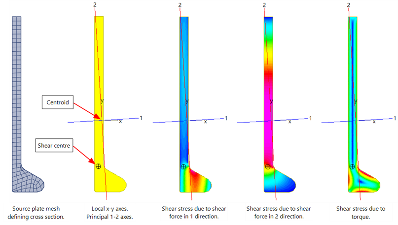
- The global axes X-Y are the axes of the global coordinate system in which the source plate mesh is defined.
- The local axes x-y are parallel to the global axes but centred on the centroid of the cross section.
- The principal 1-2 axes define the directions of maximum and minimum second moments of area, respectively, and are centred at the centroid.
- The shear centre locates the centre of twist.
Section Properties Calculated
| Quantity | Units | Notes |
| Centroid Xc, Yc |
Length |
Centre of mass for the homogeneous cross section. The local x-y coordinates where the principal 1 and 2 axes intersect mark the position of the centroid. The x-y coordinates are measured from the global origin of the source plate model, indicated by the global X-Y axes (if within the drawing range). |
| Area |
Length2 |
Area of the cross section. |
| Moments of area IXX, IYY, Ixx, Iyy, I11, I22 |
Length4 |
The second moments of area about an axis for the three axis systems: local, global, principal. For example, the second moment of area about the local x axis can be expressed as:
where |
| Product moments of area IXY, Ixy. By definition, I12=0. |
Length4 |
The cross moment of area.
where |
| Principal axis angle |
Degrees |
The counter-clockwise angle from the local x axis to the principal 1 axis. |
| Section moduli Z11, Z22, Zxx, Zyy +/- |
Length3 |
The elastic section modulus about an axis using the perpendicular distance measured from the centroid to the extreme fibres in either the positive or negative directions. For example, the section modulus about the local x axis can be expressed as:
where |
| Plastic moduli S11, S22, Sxx, Syy |
Length3 |
The plastic section modulus about an axis. For example, the plastic modulus about the local x axis can be expressed as:
where |
| Plastic modulus centroid offset PC1, PC2, PCx, PCy |
Length |
The position of the plastic modulus neutral axis measured from the centroid of the cross section such that areas above and below the axis are equal. For example, PCy is the y axis position of the plastic modulus neutral axis from which plastic modulus Sxx is calculated. |
| Radius of gyration r1, r2, rx, ry |
Length |
The area radius of gyration about an axis. For example, the radius of gyration about the local x axis can be expressed as:
where |
| Shear areas SA1, SA2 |
Length2 |
Area of the section which is effective in resisting shear deformation in the principal 1 and 2 directions. The shear area in each direction is defined as:
where |
| Shear centre offset SL1, SL2 |
Length |
Position of the shear centre measured from the centroid in the principal 1 and 2 directions; shear forces applied through the shear centre induce no torsion. The symbol  indicates the position of the shear centre. indicates the position of the shear centre. |
| Radius Area Integral rdA |
Length3 |
where |
| Torsion Constant J |
Length4 |
A term to describe the torsional stiffness of the cross section. |
| Warping Constant Iw |
Length6 |
A term to describe a section's susceptibility to warping. |
Torsion Constant J, Shear Centre, Shear Areas and Warping Constant
The Torsion Constant, J, is calculated by solving Poisson's equation for torsion of arbitrary sections. The section may include holes and can be open or closed.
The Shear Centre and Warping Constant are calculated by solving different forms of Poisson's equation using the same background finite element mesh as for the torsion constant.
The analyses produce shear stress coefficients over the section, from which the relevant section constants are calculated by integration. For example,
To produce accurate torsion constants, shear centres, shear areas and warping constants, the cross section mesh should consist of well formed regular elements with aspect ratios close to 1.0. The mesh does not need to be excessively refined because Strand7 automatically refines it before solving. Keeping the cross section mesh relatively coarse is desirable from the graphics performance point of view – coarser cross section meshes will be faster to draw.
See Also