Solvers Overview: Harmonic Response
Description
Harmonic Response analysis is used to predict the steady state dynamic response of a structure subjected to sinusoidally varying loads and base excitations.
The loading takes the following form:

where
 = amplitude of the load,
 = frequency of the load, and
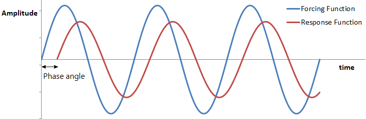
 = phase of the load.
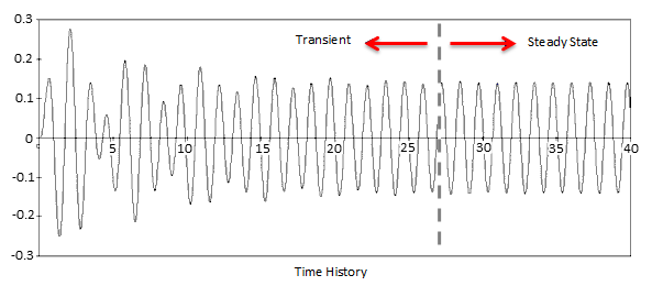
A structure typically vibrates in an irregular manner immediately after a sinusoidal/harmonic loading is applied. This is referred to as the transient response. After some time, the structure vibrates sinusoidally in sync with the forcing frequency  , but generally with different amplitudes
  and phase angles
  . This part of the response is referred to as the steady state response and takes the following form:

The Harmonic Response solver calculates the maximum values of the steady state response and the associated phase angles.
Two types of harmonic loading are available in Strand7: Applied Loads and Base Excitation. Each of these can be analysed in either the frequency domain (vs Frequency) or the time domain (vs Time).
Applied Load Excitation
All nodal, element and gravity loads are included in this type of load input, except for thermal loads and pre-loads, which are excluded. The effects of thermal loads and pre-loads are considered in terms of stress stiffening effects by the inclusion of initial conditions in the natural frequency analysis, but they are not considered for harmonic excitation.
Applied Load vs Frequency
Each applied load case may be scaled by a constant load factor and by an optional frequency dependent load factor. The frequency dependent load factor comes from a Factor vs Frequency table. This provides a way, for example, to automatically scale the centrifugal force of a rotating mass according to its angular velocity.
Each load case may also be assigned a different phase angle. This can be used for a number of purposes including the modelling of a rotating load: this can be modelled as two orthogonal loads in two separate load cases, offset by a phase angle of 90 degrees from each other, and applied at the same frequency.
The vs Frequency option calculates the effect of the loads, scaled by their associated load factors, applied simultaneously to the structure. The response is calculated at a number of frequency steps over a specified range. At each frequency step, all the loads act at that frequency, but with their own scaling factors and phase angles.
Applied Load vs Time
Each load case may be applied at a different frequency and phase angle. A zero frequency may be assigned to a load case, which implies that the load is constant, not sinusoidal. The solver calculates the contribution of each load case to the total response. This is given as magnitudes of displacements and associated phase angles; one set is calculated for each included load case. From these magnitude and phase results, the post-processor can compile a time history of response, over any time range.
Base Excitation
The structure is excited harmonically at the restrained degrees of freedom by a base excitation defined by a direction vector. The excitation can be one of base displacement, base velocity or base acceleration. This type of loading is particularly useful for modelling shaker table tests, as the base nodes are often the locations where nodal degrees of freedom are restrained.
Base Excitation vs Frequency
The base excitation direction vector sets the direction and magnitude of the base excitation. The response is calculated at a number of frequency steps over a specified range. At each frequency step, the base excitation acts at that frequency.
Base Excitation vs Time
The base excitation is applied at a single fixed frequency. The solver calculates the contribution of the base excitation to the response. This is given as one set of displacement magnitudes and associated phase angles. From these magnitude and phase results, the post-processor can compile a time history of response, over any time range.
Procedure
The Harmonic Response solver is based on the mode superposition method and executes the following steps:
- Calculates and assembles the element mass matrix if base excitation loading is applied, otherwise calculates and assembles the element load and nodal load vectors.
- Calculates modal loads and associated phase angles.
- Evaluates modal damping if Rayleigh damping is applied (see Special Topics: Damping).
- Calculates the modal displacement amplitudes and phase angles.
- Calculates modal element stresses and strains, nodal reactions, etc.
- Calculates the structure's response including nodal displacements, reactions and element stresses by combining the modal results. Both response magnitudes and phase angles are determined.
Notes
- Harmonic response analysis is based on the mode superposition method. The response of the structure is calculated by superposition of the modal responses considering their magnitudes and phase angles. This is based on a closed form solution. The choice of vibration modes used in the analysis has a significant effect on the accuracy of the results.
- The analysis relies on natural frequency results, therefore it is important to use the correct natural frequency result file.
- The same natural frequency result file can be used to run the Harmonic Response solver multiple times with different settings such as frequency range and damping.
- Theoretically, if all vibration modes are included in the analysis, the results will be exact. Otherwise the solution will only be an approximate one. Generally, more accurate results can be expected when more modes are included. To achieve reasonably accurate results, all vibration modes within and near the specified frequency range, should be included.
- The constant terms for enforced displacements, multi-point and shrink links are ignored by the Harmonic Response solver. These are treated as fixed restraints.
- The effect of material temperature dependence (see Special Topics: Temperature Dependence) on stiffness is included indirectly via its inclusion in the natural frequency analysis.
- The vs Frequency mode provides an envelope of the maximum values of the response in the result file at each forcing frequency step. When damping is included, these maximum values may not occur simultaneously and for this reason, the results for the phase angles are given. Output data includes the maximum values of nodal reaction, displacement, velocity, acceleration and phase angle as well as node and element forces, moments and stress.
- The vs Time mode calculates the magnitude of the response and phase for each included load case or base excitation. During post-processing these results may be combined to give a result in the time domain, similar to the results given by the Linear Transient Dynamic (mode superposition) solver.
See Also