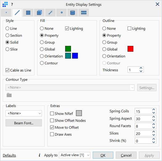
Entity Display Settings: Beam Display
Description
Configures the parameters associated with the display of beam elements.
Dialog
Style
-
Line
Draws beam elements as lines through the centroid of their cross section.
-
Section
Draws only the exterior surfaces (for hollow and solid sections) or mid plane surfaces (for open sections) of beam cross sections.
-
Solid
Draws beam elements with fully rendered and to-scale cross sections.
-
Slice
Draws beam elements as lines through the centroid of their cross section, with a 2D outline slice of the cross section shape drawn at mid-length.
-
Cable as lines
If set, cable type beam elements are drawn in either Line or Slice styles only (this effectively ignores the Section and Solid options for cables).
Fill / Outline
The fill and outline colours of the beam elements.
-
None
Does not draw the fill/outline of the elements.
-
Property
Renders the fill area or draws the outline of elements according to their respective property colours, as set under Global: Properties.
-
Group
Renders the fill area or draws the outline of elements according to their respective group colours, as set under Global: Groups.
-
Global
Renders the fill area or draws the outline of elements with a specified colour, regardless of their respective properties or groups.
To change colour, click the adjacent colour square to open the Colour Selection dialog, then select or define a colour.
-
Orientation
Renders the fill area or draws the outline at end 1 and end 2 of elements with the End 1 and End 2 colours respectively.
To change colour, click the adjacent colour square to open the Colour Selection dialog, then select or define a colour.
-
Contour
Renders the fill area or draws the outline of elements according to the quantity selected under Contour Type.
-
Lighting
If set, lighting effects defined under View Options: Drawing Tab are applied to the fill area or outline of elements.
-
Thickness
The weights of drawing lines.
Contour Type
Quantities and qualities of beam elements.
This is available when either the Fill or Outline is set to Contour.
-
List of beam quantities and qualities
-
Length
Beam length.
-
UCS Ordinate 1 / 2 / 3 Ordinate
Ordinate of beam elements in the current coordinate system (UCS).
-
EA
Modulus × Section Area in Global: Properties. Takes into account tapered beams.
-
EI1
Modulus × I11 in Global: Properties. Takes into account tapered beams.
-
EI2
Modulus × I22 in Global: Properties. Takes into account tapered beams.
-
GJ
Shear Modulus × J in Global: Properties. Takes into account tapered beams.
-
Scaled EA
Modulus × Section Area × Axial component of the beam attributes Stiffness/Mass Factor. Takes into account tapered beams.
-
Scaled EI11
Modulus × I11 × Bending 1 component of the beam attributes Stiffness/Mass Factor. Takes into account tapered beams.
-
Scaled EI22
Modulus × I22 × Bending 2 component of the beam attributes Stiffness/Mass Factor. Takes into account tapered beams.
-
Scaled GJ
Shear Modulus × J × Torsion component of the beam attributes Stiffness/Mass Factor. Takes into account tapered beams.
-
Offset 1 / 2
Applied beam offset attributes in the principal directions.
-
Stiffness Factor
Applied Stiffness Factor attributes Shear 1, Shear 2, Axial, Bending 1, Bending 2 and Torsion.
-
Mass Factor
Applied Mass Factor attributes.
-
Support / Support Gap -1 / +1 / -2 / +2
Applied beam Support attributes in the principal directions.
-
Applied Temperature
Applied node Temperature attributes at beam nodes.
-
Temperature Gradient 1 / 2
Applied Temperature Gradient in the principal directions.
-
Pre-tension
Applied Pre-load tension type attributes.
-
Pre-strain
Applied Pre-load strain type attributes.
-
Pre Curvature 1 / 2
Applied Pre-curvature in the principal directions.
-
Pipe Internal / External Pressure
Applied Pipe Pressure attributes.
-
Pipe Internal / External Temperature
Applied Pipe Temperature attributes.
-
Convection Coefficient / Ambient
Applied Convection Coefficient and Ambient Temperature attributes.
-
Radiation Coefficient / Ambient
Applied Radiation Coefficient and Ambient Temperature attributes.
-
Heat Flux
Applied Heat Flux attributes.
-
Heat Source
Applied Heat Source attributes.
-
Age at First Loading
Applied Age at First Loading (Creep) attributes.
-
Property / Material / Section Name
Labels of property, material or section name. Entries with the same name are merged to produce a plot and legend consisting of unique values.
-
Entity ID
Applied Beam ID attributes.
-
User Defined (file)
User contour data from an external file.
-
-
Settings
Contour configurations. See Result Settings: Settings.
-
User Defined (file)
Displays the full path to the user contour data file.
Labels
Displays number labels of selected type next to the beam elements.
-
Beam Font...
Opens the Settings: Font Selection dialog to adjust the font type, size, style and colour of the displayed labels.
Show NRef
If set, displays all reference nodes associated with Beam3 elements. A line is drawn from the mid-point of the Beam3 element to the reference node.
To change colour, click the adjacent colour square to open the Color Selection dialog, then select or define a colour.
Show Offset Nodes
If set, draws lines connecting the ends of the offset beam to its nodes.
To change colour, click the adjacent colour square to open the Color Selection dialog, then select or define a colour.
Move to Offset
If set, draws offset beam elements in their physical offset location.
If not set, the offset is ignored and the beam is drawn at its nodal locations.
Draw Axes
If set, displays the beam principal axes in the middle of every beam element in the model.
Spring Coils
The number of coils with which spring elements are drawn.
This option is only relevant to spring elements in either Solid or Section display styles.
Note that this option is used only for display purposes and does not affect the stiffness of the spring elements.
Spring Aspect
The aspect ratio between the length of the spring element and the diameter of its coils.
The aspect ratio ranges from 5 to 50, with 5 being the widest (i.e., 5 length : 1 coil diameter) and 50 being the narrowest (i.e., 50 length : 1 coil diameter).
Round Facets
The number of facets used to render circular sections and the number of lines used to draw spring element coils.
More facets results in an improved graphical display, but slightly longer draw times.
Slices
The number of slices used to render curved or bent beam elements such as curved pipe elements or deformed beam elements in post processing mode.
Shrink (%)
Draws individual beam elements smaller than their actual size, that is, shrunk from their nodes.
The amount of shrink is specified using a percentage scale with 0% representing no shrink, and 95% representing almost fully shrunk.
Shrink only applies to the length. The cross section is not scaled.
Common Controls
See Also