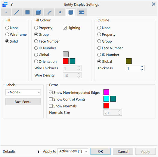
Entity Display Settings: Geometry Display
Description
Configures the parameters associated with the display of geometry faces.
Dialog
Fill
-
None
Does not draw the fill/outline of the geometry faces.
-
Wireframe
Renders the fill area of geometry faces with wireframes in the selected Fill Colour.
-
Solid
Renders the fill area of geometry faces with solid colours in the selected Fill Colour.
Fill Colour / Outline
The fill and outline colours of the geometry faces drawn.
-
None
Hides the outline.
-
Property
Renders the fill area or draws the outline of geometry faces according to their respective plate property colours, as set under Global: Properties.
-
Group
Renders the fill area or draws the outline of geometry faces according to their respective group colours, as set under Global: Groups.
-
Face Number
Renders the fill area or draws the outline of geometry faces according to their respective face number (i.e., one unique colour for each geometry face).
-
ID Number
Renders the fill area of draws the outline of geometry faces according to their respective ID number, as applied using Face Attributes: ID.
-
Global
Renders the fill area or draws the outline of geometry faces with a specified colour, regardless of their respective properties or groups.
To change colour, click the adjacent colour square to open Colour Selection dialog, then select or define a colour.
-
Orientation
Renders the fill area at the +z and -z surfaces of geometry faces with +z and -z colours respectively.
To change colour, click the adjacent colour square to open the Colour Selection dialog, then select or define a colour.
-
Wire Thickness
If Wireframe is set under Fill, defines the weights of the wireframe lines.
-
Wire Density
If Wireframe is set under Fill, defines the nominal number of wires used to represent each face. The actual number of wires drawn on a particular face depend on the size of the face with respect to the bounding box of all faces.
-
Lighting
If set, lighting effects defined under View Options: Drawing Tab are applied to the fill area or outline of geometry faces.
-
Thickness
The weights of the drawing outlines.
Labels
Displays number labels of selected type next to the geometry faces.
-
Face Font...
Opens the Settings: Font Selection dialog to adjust the font type, size, style and colour of the displayed labels.
Show Non-Interpolated Edges
If set, edges that have their edge type set to non-interpolated will be drawn with the Non-Interpolated Edge colour ignoring the Outline colour setting.
Show Control Points
If set, displays the control point polygon of the underlying surface for faces with B-spline surface definitions.
The u Lines and v Lines colours denote the u and v parametric directions of the surface, respectively. The control points cannot be edited. Note that surface offsets can make a face appear separated from its associated control point polygon.
To change colour, click the adjacent colour square to open the Color Definition dialog, then select or define a colour.
Show Normals
If set, draws the direction of the positive face normal.
To change colour, click the adjacent colour square to open the Colour Definition dialog, then select or define a colour.
-
Normals Size
Sets the relative size of the normals vector.
Common Controls
See Also