Edit: Node
Description
Edits the position of an existing node after identifying the node.
Nodes can be identified in one of two ways:
- by entering the node number directly into the Node field, or
- by clicking a node in the model window.
Both of these options will retrieve the current coordinates of the node, transform them into the active coordinate system, and place the values into the dialog. After retrieving the coordinates, the values can be edited manually before pressing Apply. They can also be edited graphically in the model window by using the Snap function, which does not require Apply.
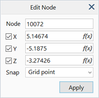
Dialog
Node
Number of the node to edit.
Coordinates (X/Y/Z)
Coordinates of the node defined in the active coordinate system.
Each coordinate may be locked by unchecking its corresponding checkbox. When locked, the value in the edit box remains unchanged even when retrieving a node with a different value for the locked coordinate. This feature enables the quick setting of a fixed coordinate for one or more nodes, by using the following sequence of steps:
- Enter the required fixed coordinate value in the edit box.
- Uncheck the corresponding checkbox to lock that value.
- Click a node in the model window for which this coordinate should be set; its other coordinate values will now populate the edit boxes on the dialog, while the fixed coordinate remains locked to the value entered at step 1.
- Press Apply; the locked coordinate is now applied to the node, leaving its other coordinates unchanged.
- Return to step 3 to repeat this for other nodes.
Equation Editor
Coordinates may be specified using equations (see Strand7 Interface: Equation Editor and Strand7 Interface: Entering Numeric Data and Formulas). Equations may contain coordinate variables as long as they do not result in self-referencing conflicts or circular definitions. For example, "3*X*Y^2" is a valid equation for the Z coordinate, whereas "5*Z" is not .
Snap
The Snap function allows for the coordinates of the node to be set graphically in the model window by using the following sequence:
- Identify the node to be edited using one of the two ways mentioned above (i.e., enter its number or click it in the model window). The mouse cursor now becomes a rubber-band line anchored at the current location of the node.
- Set the required snap target (e.g., Grid point).
- Click the target entity (e.g., a grid point); the node will now be moved immediately to the target.
- Repeat for other nodes by returning to step 1.
The snap target can be one of the following:
-
<None>
Mouse clicks in the model window do not find a target.
-
Grid point
Nodes are moved to clicked snap grid points. See Snap Grid Settings: Options Tab.
-
Other node
Nodes are moved to clicked existing nodes, overlapping the existing node.
-
Vertex
Nodes are moved to clicked vertices.
-
Entity surface
Nodes are moved to the projection of the click point onto the nearest beam, plate, brick, geometry face, or load path.
Apply
Moves selected node to the specified coordinates.
See Also