Global: Stages
Description
Used to create and define stages. A stage is a configuration of the model whereby active and inactive elements are identified using groups.
Stages are used primarily to undertake staged construction analyses using the nonlinear static solver. Stages can also be used to disable unwanted parts of a model in other solvers.
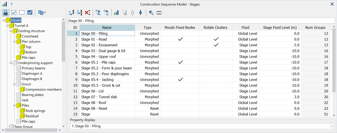
Stages are defined using the stage editor, which is a window separated into two panes - the group tree on the left and the stage list grid on the right.
Group Tree
Tree structure showing all groups defined in the model and their active/inactive state in the currently selected stage.
Groups may be collapsed or expanded by clicking on the - / + symbols next to the group name.
Lock/unlock group tree
Toggles the group tree between the locked and unlocked states.
To prevent unintended modification of the stage definition, the group tree cannot be modified when locked.
When unlocked, groups may toggled (activated or deactivated) for the selected stage by clicking the cube symbol to the left of the group name. Groups may also be toggled by pressing the Enter key or the space bar. Active groups are marked with a yellow cube, while inactive groups are marked with a grey cube.
Selections
Sets the entire group tree to active, inactive or inverts the active/inactive states.
Copy group list to clipboard
Copies the active or inactive group list to the Windows clipboard as text. The full group path is copied with the parent\child relationship indicated by the "\" separator, e.g.
Model\Tunnel A\Existing structure\Pier column\Top.
Stage List Grid
List of all stages defined in the model. A stage definition consists of stage settings and a group tree.
Add stage
Adds a new row to the bottom of the grid to create a new stage definition with a default name.
Insert stage
Inserts a new row above the highlighted cell of the grid to create a new stage with a default name.
Delete stages
Deletes stages by deleting the selected rows in the grid.
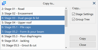
Copy to
Opens the Copy to... dialog, which allows the stage settings and/or the group tree to be copied from the current stage to one or more other stages.
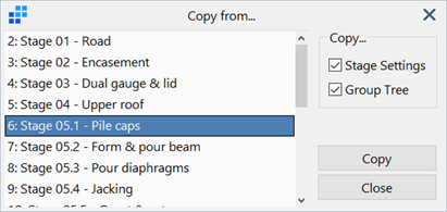
Copy From
Opens the Copy from... dialog, which allows the stage settings and/or the group tree to be copied from another stage to the current stage.
Auto Create Stages
Opens the Auto Create Stages dialog, which allows automatic creation of stage definitions based on the group tree. See Auto Create Stages Dialog below.
Invert Stage Order
Inverts the order of a selected range of stages.
Move up / down
The selected row in the grid is moved up or down in the list to change the stage order of the construction sequence. The top row is the first stage in the construction sequence.
Display Stage Definition
Updates the visibility of groups in the model window to match the group tree in the current stage. Only groups that are active in the stage group tree are shown.
This function can also be executed by double-clicking the ID cell of a stage.
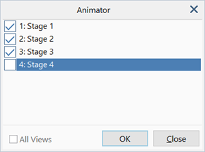
Animate Stages
Displays the Animator dialog, which allows a selection of stages to be animated in sequence. This gives a preview of what to expect from the staged analysis. See Animator Dialog below.
Property Display
This is relevant only when elements have been assigned stage-dependent properties, because in that case, the property ID of an element depends on the stage.
The dropdown list is used to set the property display stage in the model window. When <Default> is selected, the base element properties are displayed (i.e., property switches are ignored). When a stage is selected, the properties shown in the model window will take into account any property switches that may have occurred up to and including that stage.
Stage Settings - Grid Columns
ID
Identification number of a stage definition.
Name
User-defined name for the stage.
Type
There are three options for the stage type.
-
Morphed
Nodes on elements belonging to the incoming stage are morphed (i.e., smoothly formed) into new positions based on the displacements at the end of the previous stage. The incoming elements are then attached to the existing structure, and the morphed node positions become the birth coordinates of the nodes of incoming elements. The displacements at the nodes of the incoming elements are initialised to zero, so they are not loaded by pre-existing displacements at their attachment points.
Elements morphed into a stage do not change the equilibrium of the structure unless they bring additional loads with them such as weight or load through applied attributes.
The way morphed node coordinates are determined depends on the Rotate Clusters option.
-
Unmorphed
Elements belonging to the incoming stage are attached to the existing structure using their original node positions as the birth coordinates. The differences between the original node coordinates and the now displaced attachment points become initial displacements applied to the boundary of the incoming cluster of elements.
Elements that are unmorphed into a stage will change the equilibrium even if the incoming elements do not bring additional loads with them. This is due to the initial displacements from the previous stage applied to the boundary of the incoming stage. During the nonlinear iterations in the solver, these boundary displacements will propagate to the other nodes of the incoming elements, as the solver seeks the equilibrium displacements of the now combined elements.
The Rotate Clusters option is also relevant to unmorphed stages, not as a way to change the birth position of the nodes, but as a technique to help reduce excessive element distortion in the first iteration, that could occur when the incoming elements are attached.
-
Reset
Elements belonging to the incoming stage will be starting afresh as new elements in a new analysis. None of the previous morphing information, displacements or stresses are carried over. It is basically a new analysis starting from this stage. The same results would be obtained by excluding all prior stages in the stage list and running this stage as the first stage of the analysis.
The following illustrates the morphed and unmorphed options.
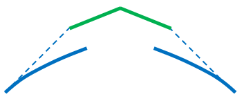
Consider the construction of a roof segment in 2D comprising three pre-fabricated components as shown below (two blue side members and one green top cap).
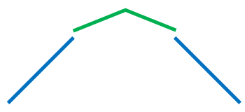
If the sides are installed first, they will bend and sag under their self-weight (solid blue) unless they supported by props. As a result, the opening for the top cap can become smaller. The undeformed geometry of the sides (dotted blue) and top cap (solid green) are drawn for reference.
When installing the top cap, there will be two options.
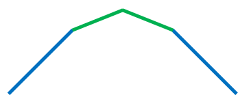
The first option would be to prop the sides back up to their undeformed positions, connect the top cap, and remove the props allowing the structure to settle to the new shape. This corresponds to the unmorphed option.
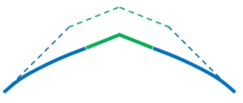
The second option would be to cut the top cap to size to fit the now smaller opening. The top cap will not be under much compression as the sides are already at the right location to attach to the cap prior to its installation. This corresponds to the morph option.
Morph Fixed Nodes
If set, and the stage is morphed, restrained nodes introduced in the stage will take part in the morphing procedure and therefore will be moved to new positions at the start of the stage. They will remain restrained after that.
If not set, and the stage is morphed, restrained nodes remain in their original position, even if nearby nodes are morphed into new positions.
If the stage is not morphed, this setting is not relevant.
Rotate Clusters
This option applies to both morphed and unmorphed stages.
For morphed stages, the option controls how the birth coordinates of elements in the incoming stage are determined.
- If Rotate Clusters is set, the average rigid body rotation of a pre-existing element connected to an incoming element is applied to the incoming element. This rotation is progressively smeared over all elements of the incoming cluster, together with the boundary displacements, to produce the birth coordinates.
- If Rotate Clusters is not set, only the boundary displacements are used. These are progressively smeared over all nodes of the incoming elements to produce the birth coordinates, without applying a rigid body rotation to the incoming cluster.
The following description illustrates this.
The model represents a cantilever constructed in two stages:
- In the first stage, the red segment is added together with the distributed load shown.
- In the second stage, the green segment is morphed into the red segment, without changing the load.
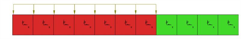
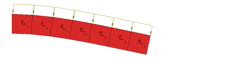
At the end of the first stage, the red segment of the cantilever deflects as shown in the following image.
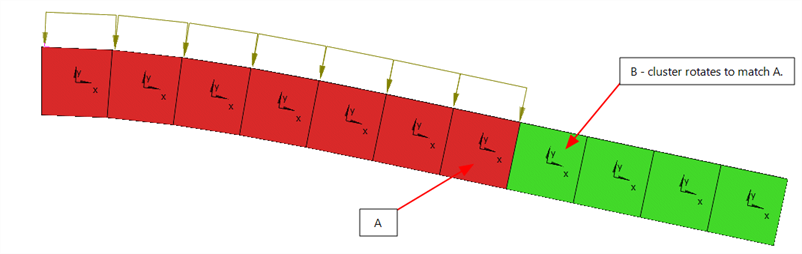
If the green segment is morphed in with the Rotate Clusters option, the combined mesh at the start of the second stage is as shown in the following image. The rigid body rotation of the element at the free end of the red segment (element A) is applied to the first element of the incoming green element (element B), which then applies it to the next green element, and so on, until the rotation has been smeared over all elements in the incoming cluster.
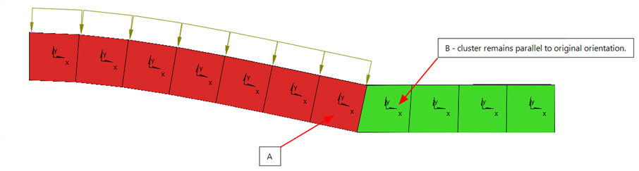
On the other hand, if the green segment is morphed in without the Rotate Clusters option, the initial orientation of the incoming green elements does not change. Instead, the displacements at the free end of the red segment are smeared without rotation to the incoming cluster, with the effect diminishing the further away a node is from the attachment point. The average translation is always applied to the incoming cluster.
In both cases (Rotate Clusters and Not Rotate Clusters), the green elements are in a stress-free state at this stage, although their shapes (i.e., birth coordinates) are different.
For unmorphed stages, the birth coordinates of the incoming stage are not modified, they remain as they were originally defined in the mesh. In that case, the displacements of the existing elements are simply applied to the incoming elements, and the solver will iterate to find the equilibrated displacements of the combined mesh. If the pre-existing displacements are large, the elements in the incoming stage can become excessively deformed to start with, to the point that a numerical solution cannot be found. To reduce this effect, the displacements at the boundaries of the existing stage are smeared over the elements of the incoming stage as an initial estimate of the deformation of the incoming stage. The solver will still iterate to find the equilibrated displacements.
The way these initial displacements are estimated for the unmorphed case follows the same procedure as that used to calculate the birth coordinates for the morphed case. After the effective birth coordinates are calculated, the difference between these and the initial coordinates of the incoming elements becomes the estimate of the initial displacements over the incoming cluster.
Fluid
The fluid level in a soil element can be set in a number of ways:
- At the property level.
- At the stage level.
- At the global level.
The fluid level defined in the property set is used whenever Fluid Level=Property Level in the property set (see Properties: Soil). In that case, the data defined at the stage and global levels is ignored.
If Fluid Level=Stage/Global Level in the property set, then either the stage level or the global level is used, depending on the setting in the stage definition.
-
Global Level
Fluid level of this stage is set to the value specified in SOLVERS Home: Fluid/Soil Parameters.
-
Stage Level
Fluid level of this stage is set to the specified stage value.
Stage Fluid level
Fluid level for the stage.
This is used when Fluid=Stage Level in the stage definition, and Fluid Level=Stage/Global Level in the element property set.
Num Groups
This is a read-only field that counts the number of active groups in the stage definition. The count updates as groups in the group tree are activated or deactivated from a stage.
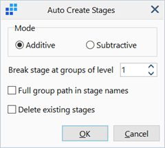
Automatically creates stages based on the group tree. A stage is created for each group at the specified break level.
Mode
Sequence of group activation in each stage.
-
Additive
Number of active groups increases with each stage, starting with one group active in the first stage, until all are activated in the final stage.
-
Subtractive
Number of active groups decreases with each stage, starting with all groups active in the first stage, until all are deactivated in the final stage.
Break stage at groups of level
Level at which to activate or deactivate individual groups for each stage.
For example, a model of a multi-storey building with the following group tree (not all groups shown):
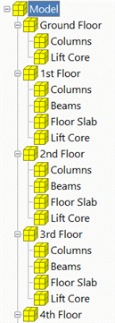
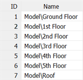
will produce the following stages when breaking at level 1:
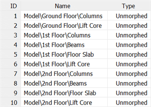
and the following stages when breaking at level 2:
Full group path in stage names
If set, the stage names are set as the full path of the group activated or deactivated in that stage. If not set, only the group name is used as the stage name. Stage names can always be edited later.
Delete existing stages
If set, all existing stages are deleted before generating the new stages. If not set, the new stages are appended to the end of the existing stage list.
Creates an animation based on the selected stages.
Stage List
List of all stages. Stages that are set are included in the animation.
Select All
Selects all stages in the list. This function is available from the right-click menu.
Unselect All
Unselects all stages in the list. This function is available from the right-click menu.
Toggle All
Toggles the selections in the stage list. This function is available from the right-click menu.
All views
If set, and the model window is currently displaying multiple views (see View: Multiview), all views are animated.
If not set, only the currently active view is animated
See Also