Special Topics: Construction Sequence
The construction sequence functionality in Strand7 can be used to simulate structural events such as the construction of a multi-storey building or a cable stay bridge, and the excavation of a tunnel or an in-ground water tank, amongst many other similar events. The functionality combines a stage editor that defines the sequence of stages for a model, together with the Nonlinear Static solver, which uses the stage information to execute the analysis.
Steps for Performing a Construction Sequence Analysis
Step 1 - Define all elements that will exist at any stage of the analysis
All elements, whether active or inactive in any stage, must be defined in the model. During the analysis, only the active nodes and elements are processed by the solver, so the solution time for each stage will be dependent mainly on the number of active elements, not the total number of elements in the model.
Step 2 - Group the elements
Groups are typically used to collect elements that belong to the same component or part of the structure, or to logically define the data structure of the entities in the model. To enable the stages to be defined, the group tree needs to be constructed so that elements can be activated or deactivated by setting the active/inactive state of the groups in which they belong. Since an element cannot belong to more than one group in Strand7, there is no possibility that an element can be both active and inactive in any stage.
Step 3 - Create the stages
The stage editor, which is accessed via Global: Stages, is used to create, delete and reorder stages. It is also used to activate and deactivate the groups that define each stage, and to specify the deformation rules and other stage dependent parameters such as the stage type (Morphed, Unmorphed, Reset).
If the group structure has been appropriately set up, the Auto Create Stages function can be used to automatically create the stages from the group tree, based on certain rules.
The stage editor also controls the property display type used for showing elements that have property switches assigned (see Step 4 below). To preview the stage sequence, the stage animation option can be executed.
Step 4 - Define staged property switches (if required)
The staging functionality in Strand7 enables elements to be activated or deactivated at any stage. It also enables elements to switch from one property type to another in a stage. For example, an element that represents soil in the current stage can be switched to concrete material in the next stage. This property switch is a more efficient way of deactivating the soil element and simultaneously activating a concrete element in its place.
Once switched, an element remains as that property in all subsequent stages until it is switched again.
Property stage switches are applied as element attributes in Beam Attributes: Property Type,Plate Attributes: Property Type and Brick Attributes: Property Type.
Step 5 - Run the Nonlinear Static solver
If stages are defined in the model, the Nonlinear Static solver can be executed for either Staged or Unstaged analysis.
In unstaged analysis, the presence of stage information in the model is ignored. A single table of load steps (SOLVERS Load: Nonlinear Static) that apply to the entire model for all load and freedom cases becomes available.
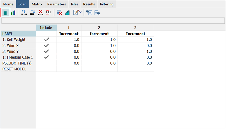
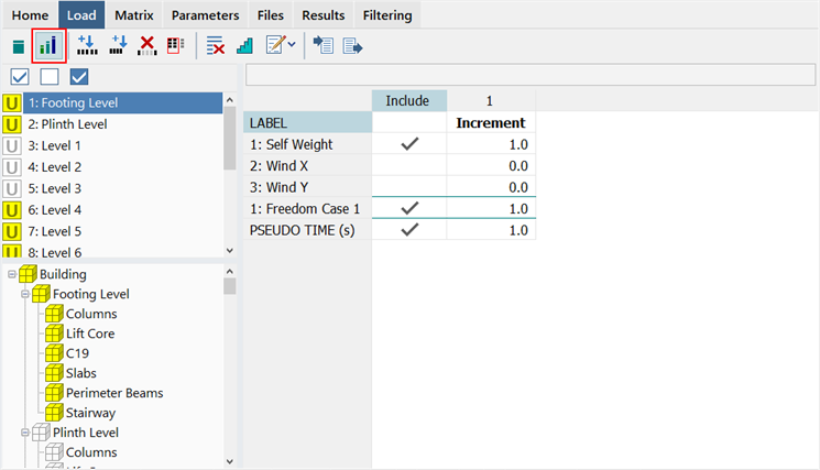
In staged analysis, the table expands to include one set of load steps for each stage. This enabled different load step sequences to be used in different stages for the active load and freedom case factors in each each stage. See the section Load and Freedom Case Activation/Deactivation below.
Via the load table, stages can be included or excluded in the analysis. An excluded stage is treated as though it is not defined in the model. If excluded stages are followed by included stages, the analysis continues to run the included stages as though they were the only stages defined in the model. The group tree shown below the stage list is for information only; stages cannot be edited here.
Step 6 - Post-process results
At the completion of the analysis, the results for all stages will be available for post-processing. It is also possible to view results while the analysis is still running, as long as some result steps have been saved to the result file.
Result options control how the inactive elements are displayed (see Result Settings: Show/Hide Tab). By default, inactive elements are nod displayed in the results graphics. There is also control on how displacement results are presented in terms of relative to their birth stage or their initial position.
Load and Freedom Case Activation/Deactivation
The staging functionality introduces the concept of the birth stage of an element - that is, the stage at which the element is first activated (note that an element can have multiple birth stages when it is deactivated and then subsequently reactivated). This concept also applies to the load and freedom cases when the Nonlinear Static solver is run for staged analysis. Load cases and freedom cases can be activated or deactivated in a stage, as required.
Although an inactivate load case is no different to an active load case with all of its load factors set to zero, that same is not true for freedom cases. A freedom case cannot be deactivated by setting its load factors to zero (what that does is to scale enforced displacements, not deactivate them). Therefore it has to be activated/deactivated by setting the relevant Include setting. In a staged analysis, an entire freedom case can be deactivated to remove all of its restraints and other freedom case dependent attributes from any stage (this includes the node and element support stiffness attributes: Node Attributes: Translational Stiffness, Node Attributes: Rotational Stiffness, Beam Attributes: Support, Plate Attributes: Edge Support, Plate Attributes: Face Support and Brick Attributes: Face Support).
When a freedom case is first activated, all node restraints defined in the freedom case are considered to be relative to the birth stage of the freedom case. In other words, if a freedom case with a fixed restraint is activated at some subsequent stage, those fixed restraints do not undo the previous stage displacements of that node. What it does is to prevent further displacement from occurring at the node; that is, the node is fixed from now on. For consistency, the same convention is applied to enforced displacements introduced at a newly activated freedom case in a stage: the enforced displacement adds to the current displacement, it does not replace it.
When node stiffness and element support attributes are used in a freedom case, the birth stage of the attributes is set to the birth stage of the freedom case. This allows, for example, for an element to be born in one stage, and then, some stages later, for its support attributes to be born. The reactions on the support attribute are based on displacements relative to the support birth stage (i.e., the stage at which the freedom case was activated), not the total displacements present at the nodes when the attributes are activated. Effectively, these attributes are treated just like elements introduced into a Morphed stage (see Global: Stages).
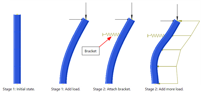
The following example illustrates the activation of a new freedom case at a later stage.
A column is pre-loaded in Stage 1 causing it to deform. In Stage 2 a bracket is attached, represented by a node translational stiffness attribute. As the deformed column is already in static equilibrium with the applied loads, the addition of the node stiffness has no effect on the result. When additional load is added in that stage, the increment in load is now carried by the complete system (i.e., by the column and the bracket together).
The load table (SOLVERS Load: Nonlinear Static) for the two stages of this model could be as follows:
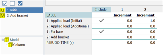
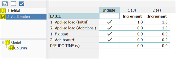
Note that in this case, there are no differences in the active groups between Stage 1 and Stage 2. The second stage is defined so that the second freedom case can be activated after the initial load in the column has been applied (no elements are added or removed).
Stage Definition for Other Solvers
The stage definitions can also be used to solve a specific part of the model using one of the other solvers. The required stage is selected from the Active Stage dropdown list in SOLVERS Home: Case Dependence. This is a convenient way of excluding elements from the analysis. If <All groups active> is selected instead of a stage name, all elements in the model are used in the analysis (this is the default case).
The following table summarises how stages can be used by each solver type, by selecting a stage in the Active Stage dropdown list:
| Solver | Usage |
| Linear Static | A stage can be selected enabling the analysis to consider only the elements in the selected stage, excluding all others. |
| Linear Buckling | The Active Stage dropdown list will be disabled but set to the stage used in the initial solution. |
| Load Influence | A stage can be selected enabling the analysis to consider only the elements in the selected stage, excluding all others. |
| Nonlinear Static | Uses stages directly in the staged analysis. |
| Quasi-static | Does not use stages directly. If an initial solution file is selected, and that solution used a stage, the Quasi-static solver continues with that stage. |
| Natural Frequency |
If no initial solution file is selected, a stage can be selected enabling the analysis to consider only the elements in the selected stage, excluding all others. If an initial solution file is selected, and that solution used a stage, the Natural Frequency solver continues with that stage. |
| Harmonic Response | Does not use stages directly. It will use the same stage as using in the natural frequency solution. |
| Spectral Response | Does not use stages directly. It will use the same stage as using in the natural frequency solution. |
| Linear Transient Dynamic | Does not use stages directly. If an initial solution file is selected, and that solution used a stage, the Linear Transient Dynamic solver continues with that stage. |
| Nonlinear Transient Dynamic | Does not use stages directly. If an initial solution file is selected, and that solution used a stage, the Nonlinear Transient Dynamic solver continues with that stage. |
| Steady Heat | A stage can be selected enabling the analysis to consider only the elements in the selected stage, excluding all others. |
| Transient Heat | A stage can be selected enabling the analysis to consider only the elements in the selected stage, excluding all others. |
See Also