Global: Create Entity UCS
Description
Creates user defined coordinate systems on selected beams, plates, bricks, geometry faces and load paths. One coordinate system is created for each selected entity.
Beam Elements
A Cartesian UCS, aligned with either the local or principal axes of the beam, is created. The origin of the UCS can be at either end of the beam or at the centroid of the beam. Beam offset attributes, if applied, are considered and the UCS is moved to the offset position.
For curved pipe elements, a cylindrical UCS may be created at the centre of curvature, in place of a Cartesian UCS.
Plate Elements
A Cartesian UCS is created aligned with the plate's local axis system. The origin of the UCS can be set to the centre, minimum or maximum positions of the UCS aligned View: Bounding Box of the plate.
Geometry Faces
Only available for analytical geometry faces (plane, cylinder, cone, sphere, torus). The type of the UCS created matches the surface type.
Load Paths
For straight load paths a Cartesian UCS is created aligned with the local load path coordinate system. A cylindrical UCS positioned at the centre of curvature is created for curved load paths.
Dialog
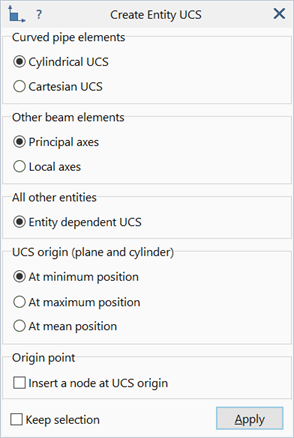
Curved pipe elements
Type of UCS to create for curved pipe elements.
-
Cylindrical UCS
Create a cylindrical UCS at the centre of curvature.
-
Cartesian UCS
Create a Cartesian UCS aligned with the local axis system.
Other beam elements
Type of UCS to create for beam elements other than curved pipes.
-
Principal axes
Create a Cartesian UCS aligned with the principal 1, 2 and 3 axes.
-
Local axes
Create a Cartesian UCS aligned with the local x, y and z axes.
All other entities
Type of UCS to create for entities other than beam or curved pipe elements.
-
Entity dependent UCS
The definition of the UCS created depends on the entity type.
UCS origin (plane and cylinder)
Position of the UCS origin when the UCS created is either a Cartesian or a cylindrical UCS.
-
At minimum position
Positions the origin at the minimum coordinate of the bounding box around the entity. The bounding box is axis-aligned with the UCS.
-
At maximum position
Positions the origin at the maximum coordinate of the bounding box around the entity. The bounding box is axis-aligned with the UCS.
-
As mean position
Positions the origin at the centre of the entity.
Insert a node at UCS origin
If set, a node is inserted at the origin of each UCS created.
Keep Selection
If set, entities remain selected after clicking Apply. Additional functions may then be applied without the need to reselect the entities. If not set, selected entities will be unselected after the function is executed.
See Also