Insert: Element

Description
Inserts beam, plate and brick elements of specified type and property.
The element is defined one node at a time by clicking on points in the model window. Points may be nodes, grid points or vertices. A new node is automatically inserted when a grid point or vertex is clicked. Existing nodes may also be selected by entering their numbers manually into the dialog.
A wireframe representation of the element is shown during insertion to aid in visualising the inserted element. Corner nodes are defined first, followed by mid-side nodes for quadratic elements. The ordering depends on the local node numbering of the element.
The element is inserted into the model once all nodes have been defined.
Dialog
Element type
Type of element to be inserted; see Entities: Beam Elements, Entities: Plate Elements, Entities: Brick Elements.
Property type
Property type number and name.
The dropdown list shows the property numbers that currently exist for the selected element type. It allows for quick selection of an existing property and is synchronised with the updown control. The updown control allows for the input of any number, even if the property does not yet exist. Selecting an item from the dropdown list automatically sets that number in the updown control; conversely, changing the updown control automatically sets the dropdown list. If a property number entered in the updown control does not yet exist, the dropdown list is cleared.
If an element with a property number that does not yet exist is inserted into the model, a new property is automatically created by default and its number is immediately added to the dropdown list.
By holding down Ctrl+Shift and clicking on an existing element in the model window, property numbers can be retrieved into the dialog using the Strand7 Interface: Hot Pointer. This enables the creation of a new element that uses the same property as an existing element.
Element group
The group to which the inserted element is added. See Target group.
Average
Automatically insert mid-side nodes on quadratic plate and brick elements at the average of adjacent corner nodes. The average position is computed using the active coordinate system. Two averaging functions are available:
-
Next
Generates one mid-side node for the next edge.
-
All
Generates mid-side nodes for all remaining edges.
Unhook
Disconnects the last clicked or auto-generated connection point and reverses the process by one step.
Cancel
Disconnects all connection points so that the element definition can start again.
Continuous mode
If set, the node that is last placed to complete an element is automatically used as the first node of the next element.
This mode is mainly useful for creating a series of connected beam elements.
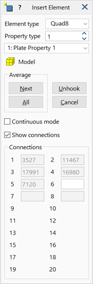
Show connections
If set, the node numbers for the element are shown during insertion.
Node numbers may be manually entered in each text box. Pressing the Enter key proceeds to the next field if a valid node number has been entered.
See Also