Selection Functions: Select by 3D Region
Description
The Select by 3D Region function defines a selection region with reference to a coordinate system. Selection operations can then be performed on entities within the region, independently of the current view angle. Entities are selected in model space, unlike Selection Functions: Select by 2D Region, which selects entities in screen space.
The coordinate system can be:
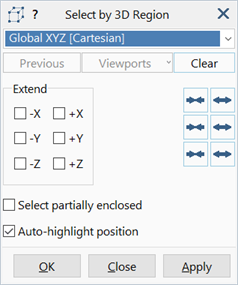
- the global XYZ coordinate system,
- any available user-defined coordinate system (UCS),
- a Cartesian system that is defined on the fly, or
- a cylindrical system that is defined on the fly.
Basic operation
The basic operation of the function can be summarised as follows:
- A coordinate system is selected.
- A region is defined with respect to that coordinate system by selecting of one or more points in the model window; points can be nodes, vertices or grid points.
- Any number of points can be selected until the desired size and shape of region is defined.
- As each point is selected, the region expands to enclose the point. Clicking a point that is already within the bounds of the region does not change the region.
- The edges of a region are always parallel to the axes of the coordinate system in which the region is defined.
- The shape of the region depends not only on the coordinate system, but also on the points used to define it.
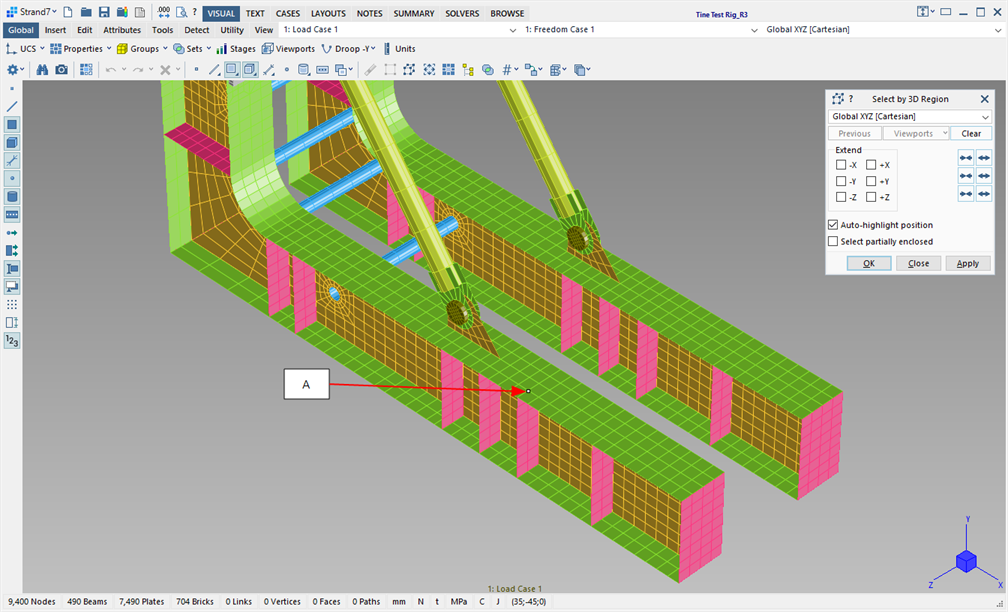
Example in global XYZ
An example of defining a 3D region in the global XYZ coordinate system is illustrated in the following images.
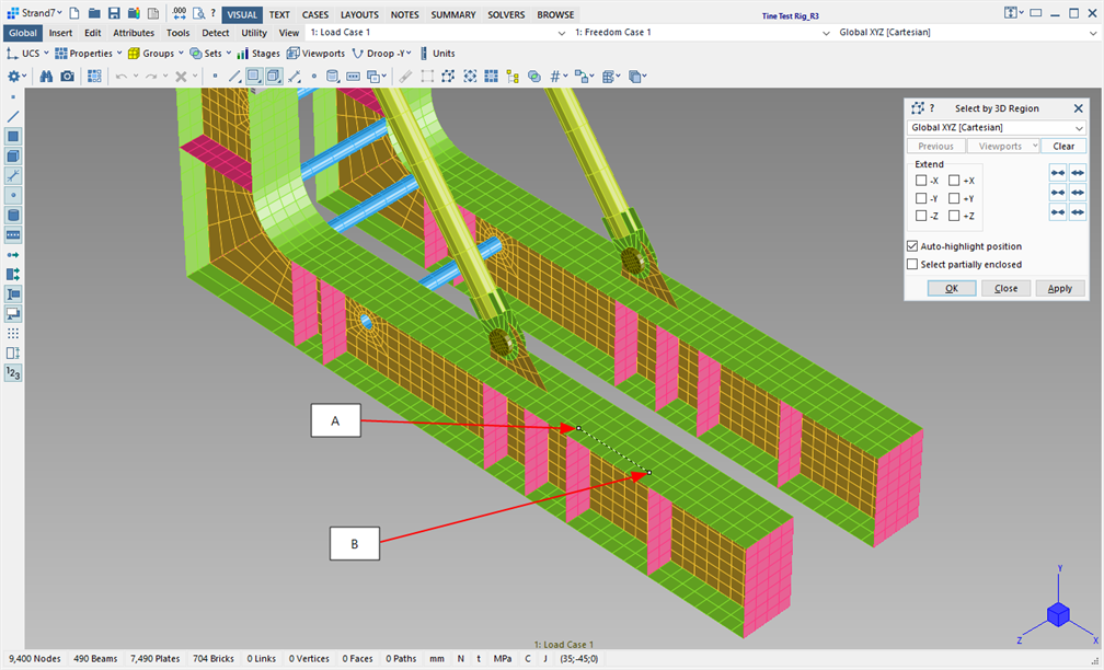
The first click point at A defines the region as a point.
The second click point at B expands the region to enclose this new point. As the second point is along the X axis with respect to the first point, the region is now a line parallel to the X axis.
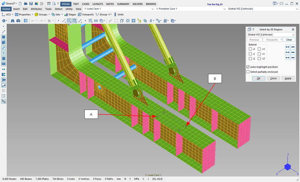
However, if the second click point at B is not along the X axis, but on the ZX plane, the region expands in two directions to enclose the point. This ensures that the edges of the region are always parallel to the coordinate system in which the region is defined. The region is now a rectangular plane with edges parallel to the X and Z axes of the XYZ coordinate system. The other two corners of the rectangle are implicitly defined.
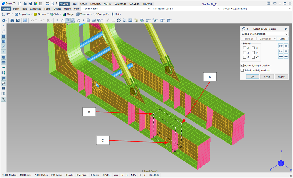
A third click point out of this plane at C, will expand the region normal to the plane, turning it into a 3D volume. Note that point C does not have to be on a corner; corner points are always implicitly defined as required.
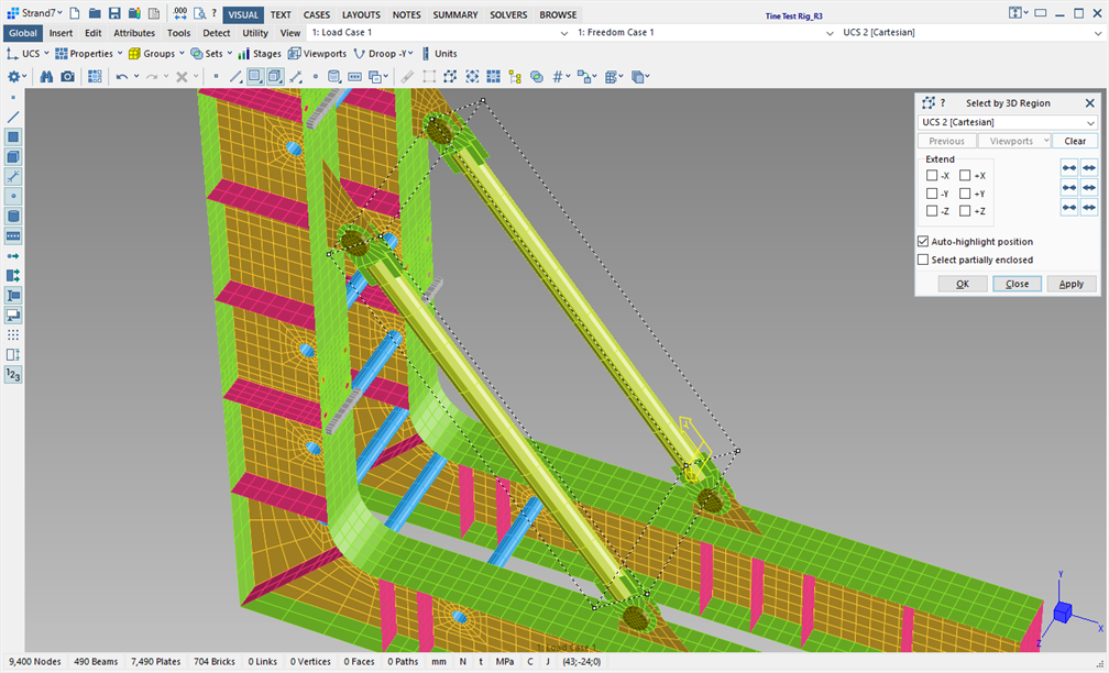
Arbitrarily orientated Cartesian UCS
Regions that reference a Cartesian coordinate system that is arbitrarily orientated in space operate in a similar way, enabling arbitrarily orientated selection regions to be defined, as illustrated in the following image.
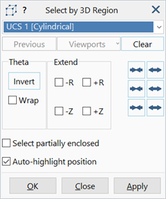
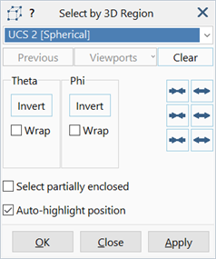
Other UCS types
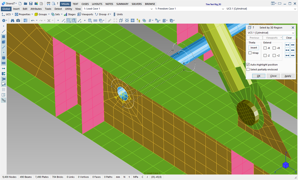
Regions that reference cylindrical, spherical or toroidal coordinate systems operate in a similar manner, except that they define different shapes. The following image illustrates a region consisting of a 270 deg sector of a cylinder.
Free Cartesian Coordinate System
A Cartesian coordinate system for use as a selection region can be defined at the same time as selecting the points, using the following rules:
- The first click point defines the origin of the coordinate system; the directions of the axes are currently undefined.
- The second click point defines the X axis of the coordinate system, and at the same time the current selection region is defined as the line between those two points. The directions of the Y and Z axes remain undefined.
- If the third click point is collinear with the first two points, the point may extend the region along the previously defined line, in which case the directions of the Y and Z axes of the coordinate system remain undefined.
- If the third click point is not collinear with the first two points, the three points now define a plane, and therefore the Y and Z axes of the coordinate system are immediately defined. The Y axis is perpendicular to the initial line, in the plane of the third point, directed towards the third point. The Z axis is perpendicular to the plane, with the positive direction given by the right-hand rule based on the X and Y axes now defined.
- From here, the Free Cartesian region behaves identically to a region referencing any other Cartesian coordinate system.
Free Cylindrical Coordinate System
A cylindrical coordinate system for use as a selection region can be defined at the same time as selecting the points, using the following rules:
- Three points must be selected; the cylindrical coordinate system is undefined until these are selected.
- After the third point is selected, a circle is fitted through those three points. The centre of the circle defines the origin of the cylindrical coordinate system. The axis of the cylindrical system is then the line passing through the origin and perpendicular to the plane defined by the first three points.
- From here, the Free Cylindrical region behaves identically to a region referencing any other cylindrical coordinate system.
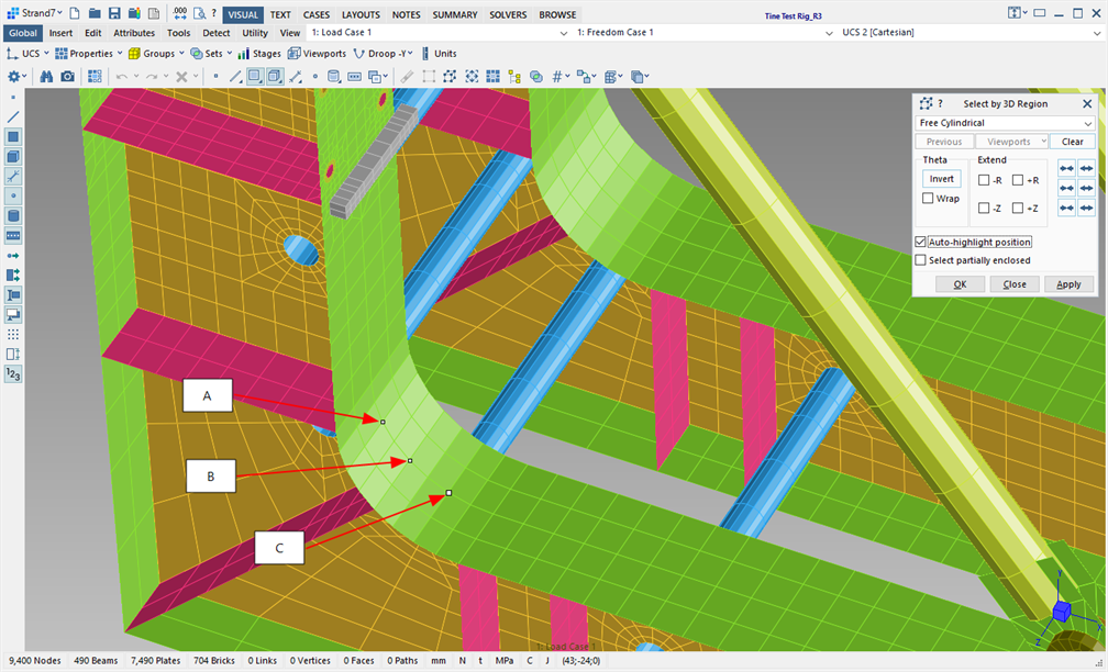
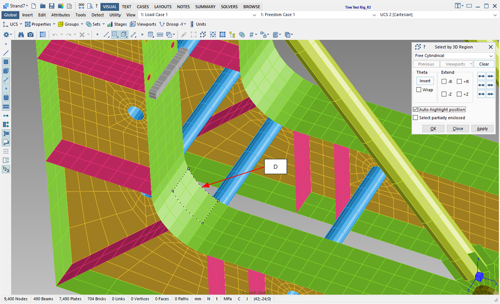
The following image illustrates the first three points selected to define a circular arc, which then defined the cylindrical system.
Clicking point D now defines a curved patch on the surface of the new cylindrical system.
Dialog
Coordinate System
The coordinate system (UCS) in which the selection region is to be defined. In addition to the global XYZ system, all user-defined coordinate systems in the model are listed, together with the Free Cartesian and Free Cylindrical options.
Previous
Sets up the current selection region as the last used region; the region can be modified further if required.
Viewports
A region previously defined for use as a Global: Viewports can be retrieved as the current selection region; once retrieved, the region can be modified further if required.
Clear
Resets the selection region to restart the region definition process; the next click point becomes the first point in the definition of a new region.
Extend
if set, indefinitely extends the dimension of the current selection region in the set direction.
Theta / Phi
These options are available for cylindrical, spherical and toroidal regions.Invert
Reverses the curvilinear extent of the region. For example, if a 270 deg cylindrical region has been defined as illustrated in the image above, by clicking Invert the region now becomes the missing 90 deg section of the cylinder.
Wrap
If set, the curvilinear extent of the region will always be 360 deg, even after selecting a single point. For example, a single click point away from the centre of a cylindrical region immediately defines a circle.
Nudge Axis 1 / 2 / 3 / - / +
Widens or narrows the selection region in the three directions depending on the type of coordinate system used. For example, to slightly enlarge a Cartesian region along its X axis, click the Nudge Axis 1 (+) icon. To keep enlarging it, click and hold the icon.
Using the combinations Ctrl + Nudge Axis 1, 2 or 3 or Alt + Nudge Axis 1, 2 or 3, allows one side of the selection region to be fixed while stretching or shrinking the selection region from the opposite side with respect to the active axis. The Alt key operates on the positive side of the region, whereas the Ctrl key operates on the negative side of the region.
Select partially enclosed
If set, an entity is selected if any part of the entity is inside the region.
If not set, an entity must be fully enclosed by the region before it can be selected.
Auto-highlight position
If set, the coordinates of points (nodes, vertices and grid points) are displayed via the Strand7 Interface: Entity Inspector as the mouse passed over them, without pressing the Shift key. This facilitates the detection of click points to define the 3D region.
See Also