Align Tools: Plate Axes by Connection
Description
Aligns the local x and y axes of selected and interconnected plate elements based on the axes of adjacent plate elements.
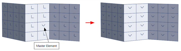
Starting from a master plate element within the selected set, the axes of the master plate are projected to selected elements directly connected to it; those elements then project their axes onto their own connected elements, and so on, until all selected and interconnected elements have had their axes aligned. The alignment takes into account the spatial orientation of adjoining elements so that the axes of 3D faceted shell models can be aligned using this tool.
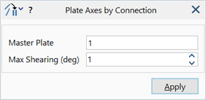
Dialog
Master Plate
The plate element number that is the source of the alignment.
The master element must be part of the set of selected elements.
Max Shearing (deg)
An angle in degrees.
This parameter is relevant only when aligning the axes of plate elements on a surface with double curvature.
The action of projecting the local axes from element to element is analogous to the draping of a flat sheet over the surface. If the surface is doubly curved, the sheet cannot be draped without shearing it in its plane; the amount of shearing is a function of the radius of curvature for the surface, and can be measured as the angular change to two initially orthogonal lines (the axes) drawn on the flat sheet before draping.
If the shearing action on an element exceeds this angular measure, the element's axes are not aligned, the element remains selected and a warning is given.
Common Uses
The orientation of the local axes is important as it determines the direction of the local output stresses, moments and forces. The axes are also used for orientating orthotropic and laminate materials, amongst others.
See Also