Extrude Tools: by Projection to UCS


Description
Extrudes selected nodes, beams, plates and brick faces by projecting them onto a target surface defined by a UCS, in a specified direction.
The target surface may be a plane (Cartesian UCS), a cylinder (cylindrical UCS) or a sphere (spherical UCS).
Nodes are extruded into beams or links, beams are extruded into plates, and plates and brick faces are extruded into bricks.
Projection is undertaken on a node by node basis and the result depends on both the source and how the target direction is defined, as described in Tools: Project to UCS.
Dialog
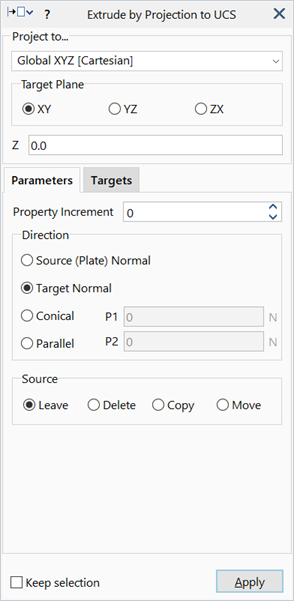
Coordinate System
The coordinate system used to define the target surface.
A Cartesian, cylindrical or spherical coordinate system may be selected.
Target Plane XY / YZ / ZX
The Cartesian plane to use as the target surface.
Applicable only if a Cartesian UCS is selected.
X / Y / Z
Normal position of the target plane. For example, an XY plane is positioned along the Z axis.
Applicable only if a Cartesian UCS is selected.
Radius
The radius of the cylindrical or spherical target surface.
Applicable only if a cylindrical or spherical UCS is selected.
Direction
Projection direction. Both positive and negative directions are considered for each case.
-
Source (Plate) Normal
Direction is defined by the average normal of all plate elements connected to the source node.
Only applicable to nodes on plate elements. If the source node does not have plates attached, the direction is undefined and no projection is applied.
-
Target Normal
Direction is normal to the target UCS, passing through the source node.
-
Conical
Direction is defined by the vector from the Apex point to the source node.
-
Parallel P1 / P2
Direction is defined by the vector from point P1 to point P2.
Common Controls
- Components
- Point selection
- Property Increment
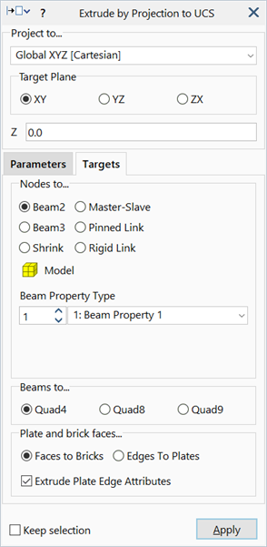
- Extrude Plate Edge Attributes
- Source
- Nodes to...
- Beams to...
- Plates and brick faces...
- Keep Selection
See Also