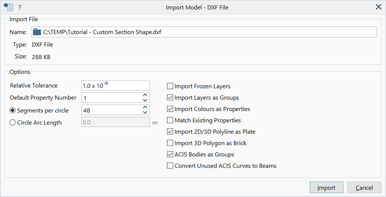
Import: AutoCAD DXF File

Description
Imports an AutoCAD DXF (Drawing eXchange Format) file with file extension of .dxf.
Polylines and 3DFACE entities are imported as equivalent beam, plate and brick elements. 3DSOLID entities are imported as geometry faces.
Dialog
Name
Opens the file dialog to locate and select the DXF file to be imported. Note that files can also be imported by using drag-and-drop directly onto the Strand7 model window or startup screen (see Strand7 Interface: Startup Screen).
Relative Tolerance
A length tolerance is used to set the accuracy of various operations performed during import. These include curve fitting (setting the accuracy of an interpolated curve), vertex insertion on edges (setting the maximum allowable mismatch between the point on the edge and the corresponding vertex point), and the zipping of overlapping edges. This length tolerance is calculated as the Relative Tolerance times the maximum dimension of the bounding box of the imported geometry. A smaller tolerance produces a more accurate geometry (where possible), but fewer edges may be zipped. Zipping of edges can always be performed after importing, if required, using Clean Tools: Geometry. The default value is 1.0E-6.
Default Property Number
The property number assigned to imported entities if no other instructions are found.
Segments per Circle
Number of segments per full circle to control the number of beams generated to represent curves.
In cases of an arc, i.e., part circle, the number of segments is calculated as the nearest integer multiple of segments determined by the ratio of the length of the arc to the circumference of a circle with the same radius.
Circle Arc Length
Nominal length of beam element on the curve. The number of segments is calculated as the nearest integer multiple of segments determined by the ratio of the requested Circle Arc Length to the length of the arc.
Import Frozen Layers
If set, frozen layers are treated as normal layers and imported.
Import Layers as Groups
All geometry imports into Strand7 are placed into a new group, as a child group of the root group. The name of this new group will be based on the name and type of the imported file, and is referred to as the default import group. The imported DXF file may have a grouping structure of its own, in which case this structure can be imported as child groups of the default import group.
If the option is set, one new group is defined for each layer in the DXF file. Each new group will become a child group of the default import group.
If the option is not set, or if DXF layers information is not available, imported entities are assigned to the default import group.
Import Colours as Properties
If set, property numbers are assigned to imported entities based on their layer colours as defined in the DXF file.
Entities of the same colour are assigned the same property number. Same colour means identical RGB values, and these RGB values are also used to define the property colour of the geometry faces.
The names of automatically generated plate property data sets is also based on these colours; they will be given a name such as "DXF Index Colour XXX" where XXX is a number (one of 256 standard DXF colour indexes) , or "DXF True Colour #XXXXXX" where #XXXXXX is a hexadecimal string representing the RGB colour (for example, "DXF True Colour #C0C0C0" represents a grey colour).
Match Existing Properties
If set, and Import Colours as Properties is also set, new properties are created only if a matching property (i.e., a property with the required colour) does not already exist in the model. This option is useful when importing multiple files into one Strand7 model allowing properties (i.e., colours) from the different imports to be matched.
Import 2D/3D Polyline as Plate
If set, 2D/3D polylines are converted to Tri3 and Quad4 elements, respectively (where possible).
Import 3D Polygon as Brick
If set, 3D polygons are converted to brick elements (where possible).
ACIS Bodies as Groups
All geometry imports into Strand7 are placed into a new group, as a child group of the root group. The name of this new group will be based on the name and type of the imported file, and is referred to as the default import group. If the imported DXF file contains ACIS entities with a grouping structure of their own, this grouping structure can be imported as child groups of the default import group.
If the option is set, one new group is defined for each ACIS Body entity, and geometry faces within each body are assigned to that group. In a well-defined solid model, this will result in each solid being assigned to its own separate group. Each new group will become a child group of the default import group.
If the option is not set, or if ACIS Bodies information is not available, imported geometry is assigned to the default import group.
Convert Unused ACIS Curves to Beams
If set, unused curves in the imported DXF file that contains ACIS entities are imported as beam elements.
Unused curves are curves that are not referenced in the definition of any face in the file. If all curves in the ACIS entities are referenced, this option has no effect.
See Also