Results Interpretation: Beam Slices
Description
Forces and moments can vary along the length of a beam element. As such, results along the beam element, in addition to those at the ends, are also of interest. Results along the beam element are reported at evenly spaced beam stations (slices) with and option to automatically include additional stations (slices) to capture points of interest such as maximum bending moment and shear force transitions.
The number of equi-spaced slices can be set in various locations based on the post-processing operation being performed (for example, for plotting force diagrams on beams, the value can be set in Element Result Settings: Entity Tabs; for extracting data in The LISTINGS Tab a listing specific setting can also be set).
The option to include additional beam stations (slices) to capture points of interest is available on The LISTINGS Tab and in the Results Options: Envelopes Tab.
Example
A 1.0 m long simply-supported beam element has two load cases:
-
Load case 1:

-
Load case 2:

Bending Moment and Shear Force Diagrams
The number of beam slices, including the beam ends, for the display of beam forces and moments diagrams can be configured under Element Result Settings: Entity Tabs.
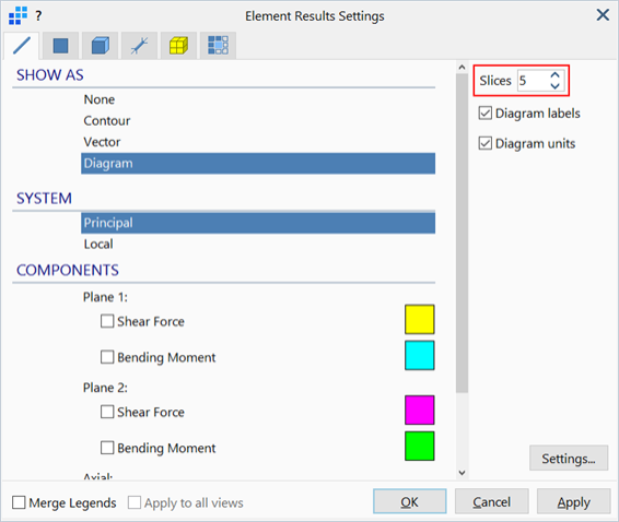
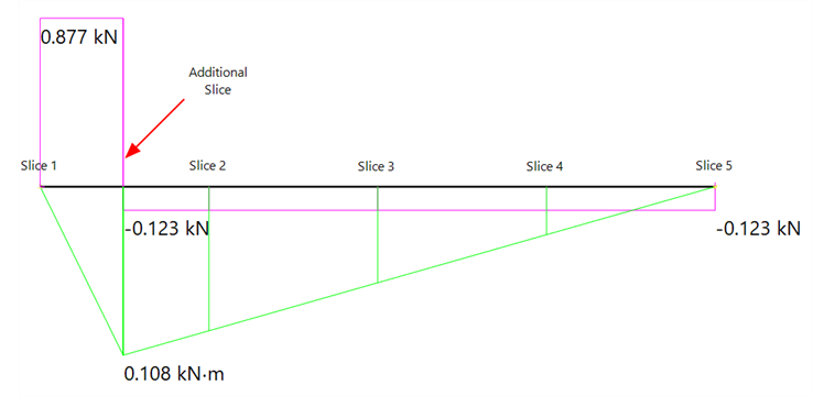
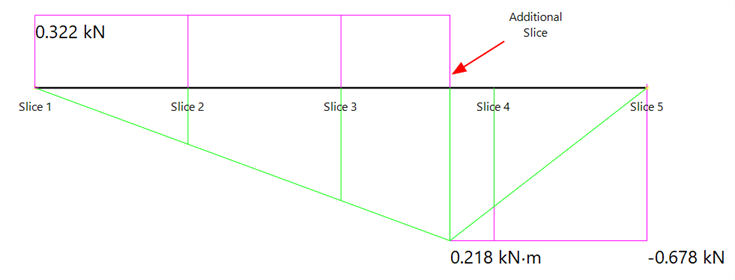
In addition to the specified number of slices, the diagram display always includes additional slices that capture the peaks and transitions. An exception to this is envelope results, which include or exclude the additional beam slices based on the user requested option (see Envelope Cases section below for details).
-
Results case 1:
-
Results case 2:
Results Listings
Similarly, the number of beam slices, including the beam ends, in The LISTINGS Tab can be configured by clicking the current setting ![]() . The listings can be configured to show only results at the specified slices or to also add additional stations (slices) to capture result peaks and transitions. Note that this setting does not apply to envelope results (see Envelope Cases section below for details).
. The listings can be configured to show only results at the specified slices or to also add additional stations (slices) to capture result peaks and transitions. Note that this setting does not apply to envelope results (see Envelope Cases section below for details).
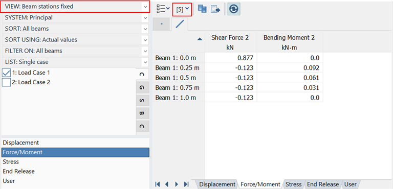
Take results case 1 for example:
-
VIEW: Beam stations fixed:
-
VIEW:Beam stations plus:
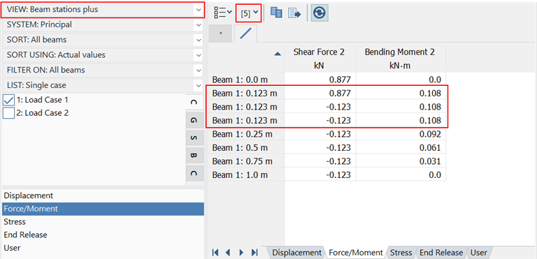
In the above listing, a new point has been inserted at 0.123 m, in addition to a point slightly below 0.123 m and another point slightly above 0.123 m. Using three decimal digits, these three points all appear the same. This point is where the shear force discontinuity occurs.
Envelope Cases
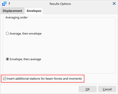
Similarly to results listings, envelope results can be configured to include or exclude additional slices under Results Options: Envelopes Tab. Due to the processing time required for large enveloping calculations, envelope results are not automatically re-generated and must be updated under CASES: Envelope Cases each time this setting is changed.
-
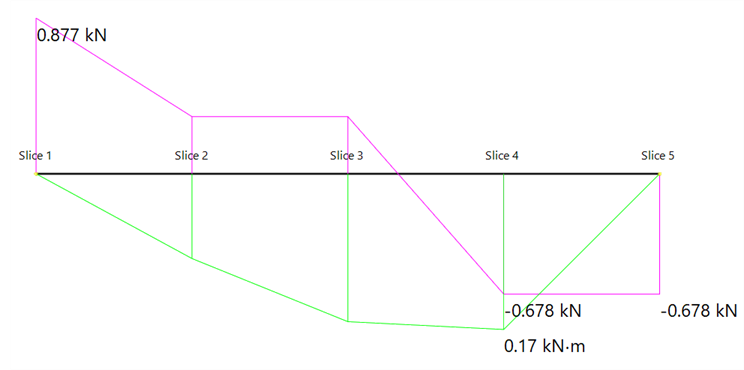
Envelope diagram without additional stations is shown below with 5 default slices.
-
Envelope diagram with additional stations is shown below with 5 default slices in total. A total of 7 slices are produced.
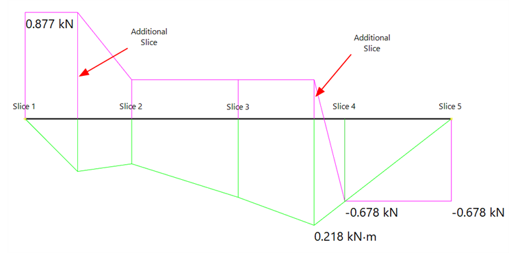
Note that envelope results are only calculated at the beam stations (slices) and so results in between the stations (slices) are displayed as linearly interpolated.
See Also