Special Topics: Moving Load Analysis
Description
The Moving Load module allows detailed specification and analysis of loads moving along prescribed paths. The Insert: Path and LAYOUTS: Paths, combined with the SOLVERS: Load Influence Settings or one of the time-dependent solvers, provides a simple but highly effective means of performing moving load analysis.
- The moving load module is designed to support a range of design codes including AS 5100, BS 5400, EN 1991 and AASHTO LRFD Bridge Design Specifications.
- Load Paths are independent of the underlying mesh.
- Load Path Templates support vehicle definitions in multiple lanes consisting of structural and heat transfer loads, such as point forces, distributed forces and heat sources.
- Load influence analysis can be performed with the Load Influence solver to produce influence lines and influence surfaces corresponding to node and element response variables.
- Load Influence Combinations can be generated from the load influence solution and Load Paths to determine critical load combinations.
- Time-dependent or dynamic analysis can be performed using the SOLVERS: Quasi-static Settings, SOLVERS: Linear Transient Dynamic Settings, SOLVERS: Nonlinear Transient Dynamic Settings and SOLVERS: Transient Heat Settings.
Load Paths
A Load Path is created in a similar way to an element. Load Paths can be selected independently of the entities that they overlay. They are Load Case dependent, and can also be grouped, copied, moved and scaled just like elements.
Load Path attributes such as the Path Attributes: Template Type, Path Attributes: Group, Path Attributes: Apply Load To and Path Attributes: Divisions can be modified after creating the Load Path.
A Load Path can be created over any element type (beam, plate and brick). The path can be straight, circular or parabolic, and either flat or curved.
The Load Path is independent of the mesh density. This means that if the Load Path only partially lies on an element, the proportional amount of load is transferred to that element. Importantly, it also means that changes to the mesh do not require a redefinition of the Load Path.
See Insert: Path.
Path Templates
Path templates are associated with one or more load paths (see LAYOUTS: Paths). Path templates can accommodate moving load codes AS5100, BS5400, EN 1991 and AASHTO LRFD Bridge Design Specifications, as well as user-defined load and axle spacing configurations. The following points highlight the main features of the path template:
- Multiple vehicles can be defined for each path template.
- Vehicles can consist of a combination of point forces, distributed forces and heat sources.
- Point forces can be specified as Grouped or Floating. Distributed forces can be specified as Grouped, Leading, Trailing, Full Length or Floating . Heat sources are always Grouped .
- Grouped loads move together according to their relative positions. Floating point forces can move independently along the length and width of the load path. Floating distributed forces can only move along the length of the load path.
- Full length distributed forces are applied to the entire length of the load path. Leading and trailing distributed forces lead and trail the grouped loads (point forces, distributed forces and heat sources) to the extents of the load path.
- Void regions between leading and trailing distributed loads can be generated by defining zero magnitude grouped loads.
- Point forces and distributed forces can be defined in the local and global coordinate systems. This allows for the definition of not only vertical loads but also braking and centrifugal loads where required.
- Load options allow for code compliant Vehicle load definitions, including Type HA and Type HB vehicular loads and railway loads used in BS 5400.
- A range of pre-defined path templates according to codes AS 5100, BS 5400, EN 1991 and AASHTO LRFD Bridge Design Specifications are available.
- Up to 16 lanes of fixed width can be specified per path template.
- Load factors for each lane can be specified according to the number of active lanes.
- Vehicles can be specified in single or multiple lanes and can straddle adjacent lanes.
- Vehicles can be placed in Sets such that only the vehicle that determines the worst case loading is selected from the set.
- Vehicle directions, start time and velocity can be specified for full dynamic moving load analysis.
See LAYOUTS: Paths.
Factor vs Time Tables
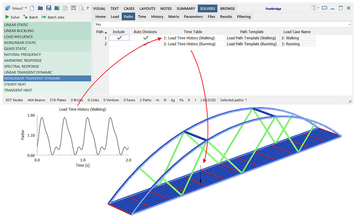
In SOLVERS: Quasi-static Settings, SOLVERS: Linear Transient Dynamic Settings and SOLVERS: Nonlinear Transient Dynamic Settings, Factor vs Time tables (LAYOUTS: Tables) can be assigned to load paths to vary the load magnitude of vehicles over time. With this option, load can vary in both position and time in these solvers. This is particularly useful in the modelling of surface irregularities and pedestrian footfall. An example of applying a ground reaction function due to walking gait to a load path is shown below.

See Also