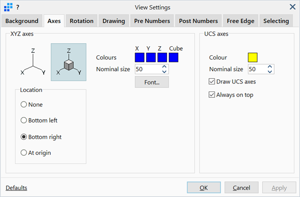
View Settings: Axes Tab

Description
Configures the display of global and user-defined coordinate systems in the model window.
Dialog
XYZ axes
Display style of the global XYZ axes.
-
Location
The position at which the global XYZ axes are drawn.
If None is set, the axes are not drawn.
If Bottom left or Bottom right are set, the axes are drawn at the bottom left or bottom right corners of the model window, respectively.
If At origin is set, the axes are placed at the global Cartesian origin (0, 0, 0).
-
Colours
Sets the colours used to draw the axes. Colours for each axis and for the cube can be set independently.
To change colour, click the colour square to open the Colour Selection dialog, then select or define a colour.
-
Nominal size
Sets the nominal size of the axes in number of pixels.
-
Font...
Opens the Settings: Font Selection dialog to adjust the font type, size, style and colour of the labels drawn on the axes.
UCS axes
Display style of the user-defined coordinate system (UCS) axes.
-
Colour
Sets the colour in which the axes are drawn.
To change colour, click the adjacent colour squares to open the Colour Selection dialog, and select or define a colour.
-
Nominal size
Sets the nominal size of the axes in number of pixels.
-
Draw UCS axes
If set, UCS axes are displayed in the model window at the origin of the UCS.
If not set, UCS axes are not drawn.
-
Always on top
If set, UCS axes are always drawn on top of all other entities so that they remain visible at all times.
If not set, UCS axes are drawn in the 3D space in which they are defined. This means they can be fully or partially obscured by other entities such as elements and geometry faces.
Common Controls
See Also