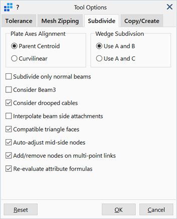
Tool Options: Subdivide Tab
Description
Options used by Mesh Tools: Subdivide.
Dialog
Plate Axes Alignment
This option is applicable to quadrilateral plate elements only.
-
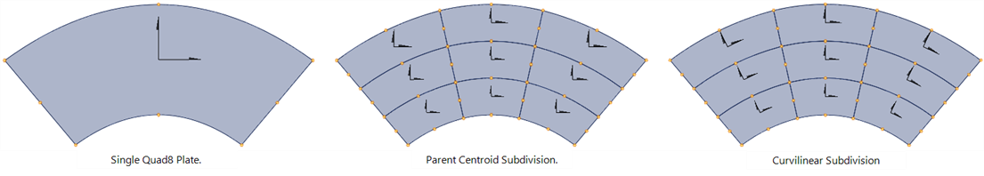
Parent Centroid
Subdivided elements inherit the local axes alignment of the parent and therefore all resulting elements will have their local system parallel to each other.
-
Curvilinear
The local x axis of subdivided elements is aligned with the first curvilinear axis of the natural coordinate system. For a curved (quadratic) element, this results in a series of local axes (non-parallel) curving around the element.
Wedge Subdivision
This option is applicable to wedge elements only; the parameters A, B and C refer to the Mesh Tools: Subdivide dialog.
-
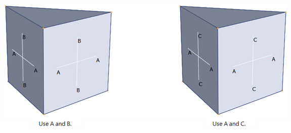
Use A and B
Parameter A is used for the subdivision of the triangular face; parameter B is used for the subdivision of the rectangular face.
-
Use A and C
Parameter A is used for the subdivision of the triangular face; parameter C is used for the subdivision of the rectangular face.
Subdivide only normal beams
If set, only normal type beam elements are considered for subdivision. All other types of beam elements (e.g., truss, point contact, connection, spring-damper) are excluded.
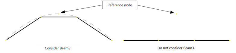
Consider Beam3
If set, Beam3 elements are subdivided along a parabola fitted through the end nodes and the reference node.
If not set, Beam3 elements are sudivided as Beam2 elements, along the straight line between end nodes.
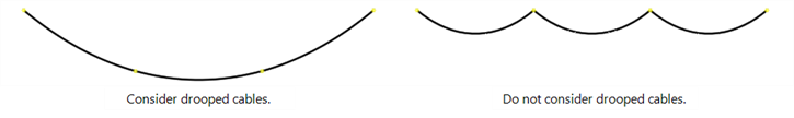
Consider drooped cables
If set, cable elements are subdivided according to the initial cable droop line.
If not set, cable elements are subdivided at straight-line intervals between the two ends.
For both options, the sum of the free lengths of the subdivided cables equals the initial free length of the single cable.
Interpolate beam side attachments
If set, existing beam side attachments are applied to subdivided beams with the Max Gap distance linearly interpolated between the two original ends, provided that the side attachments are in the same direction.
If not set, beam side attachments remain only on the original ends of the beam before subdivision.
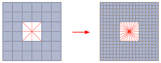
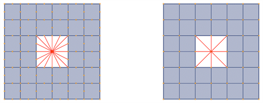
Compatible triangle faces
This option controls the subdivision of triangular plate elements and wedge brick elements, as illustrated in Mesh Tools: Subdivide.
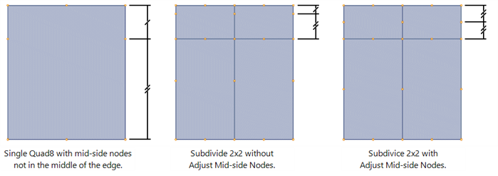
Auto-adjust mid-side nodes
If set, the subdivision operation will reset the position of the mid-side nodes of the elements to be 'mid-way between the corner nodes'. For straight edges, the mid-side node will be positioned mid-way along the straight line between corner nodes. For curved edges, the mid-side node will be positioned mid-way along the circular arc passing through the three nodes before adjustment.
The reason this feature is available is that when subdividing quadratic elements, the mid-side nodes will influence both the mesh grading and the default position of the mid-side nodes on the subdivided elements. This is because the element is subdivided in parametric space, not in model space. In the following figure, a single Quad8 (left image) is subdivided into a mesh of 2x2 Quad8. The mid-side nodes on the vertical edges of this element are not in the middle, but shifted upward. The default subdivision, that is, the one without adjusting mid-side nodes, produces the mesh in the centre image - the mid-side nodes on the subdivided elements are also shifted, similarly to the initial element. If the option to adjust mid-side nodes is set, the mesh shown in the right image is produced - here the mid-side nodes are in the middle of the edge.
Add/remove nodes on multi-point links (MPL)
If set, additional MPL nodes on subdivided elements are automatically added, whilst redundant nodes are automatically deleted from then MPL as required.
Additional link nodes are generally added when subdividing to increase the mesh density.
When subdividing for the purpose of reducing the element order (e.g., converting Quad8 to Quad4) redundant nodes will be generated at the mid-side nodes, and these can be automatically deleted.
Re-evaluate attribute formulas
If set, saved attribute formulas are re-evaluated and attribute values are re-assigned after the subdivision operation.
See Also