Mesh Tools: Subdivide
Description
Subdivides selected beam, plate and brick (source) elements along their local axes to produce a refined mesh of (target) elements.
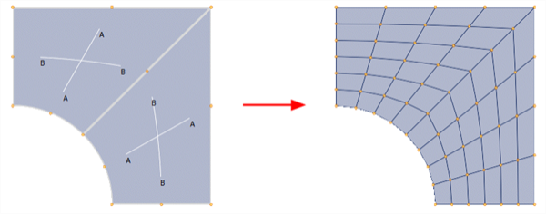
Element attributes applied to the source elements are transferred to the target elements. For example, plate normal pressure on a source element is transferred to all of its target elements; plate edge pressure on a source element is transferred to the appropriate edges of target elements.
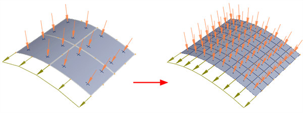
Node attributes (e.g., temperature and restraints) are linearly interpolated as appropriate.
Elements can be converted from one type to another if a valid subdivision exists. For example, a Quad8 can be converted to a Quad4.
Dialog
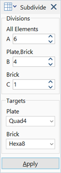
Divisions (A / B / C)
Number of divisions in each direction of the element's default local axis system, which is defined only by the element's node connection order; attributes that modify the local system (such as local axis angles) are ignored for the purpose of subdivision. The usage of A, B and C by the various source element types is as follows:
-
Beam Elements
Direction A specifies the number of divisions along the length of the beam.
Directions B and C are ignored.
-
Plate Elements - Tri
Direction A specifies the number of divisions along all three edges of the element.
Directions B and C are ignored.
-
Plate Elements - Quad
Directions A and B specify the number of divisions along the edges parallel to the element's default local x and y axes, respectively.
The A and B directions can be rotated by 90 degrees using Align Tools: Rotate Plate Connections.
Direction C is ignored.
-
Brick Elements - Tet4 / Tet10 / Pyra5 / Pyra13
Direction A specifies the number of divisions along all edges of the element.
Directions B and C are ignored.
-
Brick Elements - Wedge6 / Wedge15
Direction A specifies the number of divisions along all edges of the triangular face.
Directions B or C specify the number of divisions along the remaining edges of the rectangular faces. The choice to use either B or C is made in Tool Options: Subdivide Tab.
-
Brick Elements - Hex8 / Hex16 / Hex20
Directions A, B and C are used for the edges parallel to the three local directions, respectively.
Targets - Plate
Element type to generate as a result of subdividing source plates.
-
Tri3 / Tri6 / Quad4 / Quad8 / Quad9
Target elements are converted to the selected element type, where possible.
-
Source
Target element type is the same as the source element.
-
Tri
Target elements are converted to triangular elements, with the order of the target element being that of the source element (i.e., linear source elements produce Tri3, and quadratic source elements produce Tri6).
-
Quad
Target elements are converted to quadrilateral elements, where possible, with the order of the target element being that of the source element (i.e., linear source elements produce Quad4, and quadratic source elements produce Quad8 or Quad9).
Targets - Brick
Element type to generate as a result of subdividing source bricks.
-
Tetra4 / Tetra10 / Wedge6 / Wedge15 / Hexa8 / Hexa16 / Hex20
Target elements are converted to the selected element type, where possible.
-
Source
Target element type is the same as the source element.
-
Tetra
Target elements are converted to tetrahedral elements, with the order of the target element being that of the source element (i.e., linear source elements produce Tet4, and quadratic source elements produce Tet10).
-
Wedge
Target elements are converted to wedge elements if a subdivision is possible, with the order of the target element being that of the source element (i.e., linear source elements produce Wedge6, and quadratic source elements produce Wedge15).
-
Hexa
Target elements are converted to hexahedral elements, if a subdivision is possible, with the order of the target element being that of the source element (i.e., linear source elements produce Hexa8, and quadratic source elements produce either Hexa16 or Hexa20).
Right Click Menu
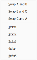
Right clicking the dialog reveals some additional functionality that can be used to quickly define a subdivision.
-
Swap
Swap two values between the A, B and C directions.
-
Presets
Quickly set a uniform subdivision (e.g., 2×2×2).
Valid Source-Target Combinations
Beam Source-Target Combinations
Beam element targets are always the same element as the beam element source. However, special consideration can be given to some source type beams by setting the related options in Tool Options: Subdivide Tab.
-
Subdivide only normal beams prevents other beam types (e.g., truss, point contact, spring) from being subdivided. This can avoid having to deselect non-beam elements when subdividing the whole model.
-
Consider Beam3 treats the reference node on Beam3 elements as the mid-point along a parabolic line; the subdivision then produces a parabolic line of beam elements. This can be a useful modelling tool.
-
Consider drooped cables is similar to Consider Beam3, but controls whether a drooped cable will be subdivided along its droop line or as a straight line between the nodes.
In addition, curved pipe elements are always subdivided along the curved path producing curved shorter pipe elements with the same curvature.

Plate Source-Target Combinations
Quadrilateral source plate elements can produce plate targets of any type, for any number of A and B divisions.
Triangular source plates have the following specific cases:
-
When A divisions is 1, quadrilateral targets cannot be produced; in that situation the target produced will have the same order as the requested target, but remains a triangle (e.g., requesting a Quad8 target will produce a Tri6 element for both Tri3 and Tri6 source types).
-
When the target is triangular, the subdivision proceeds as illustrated below, no matter the value of A divisions.

-
When the target is quadrilateral, and A divisions is an even number, the triangle will be divided into three quadrilaterals, and then each quadrilateral is further subdivided into quadrilaterals to produce the requested number of (A) edge divisions.

-
When the target is quadrilateral, and A divisions is an odd number greater than 1, the resulting subdivision depends on the Compatible triangle faces option in Tool Options: Subdivide Tab.
If Compatible triangle faces is set, the subdivision ignores the quadrilateral target request and instead produces triangles.

If Compatible triangle faces is not set, the subdivision produces a mixture of quadrilateral and triangular targets as illustrated below.

Brick Source-Target Combinations
Hexahedral source elements can produce brick targets of any type except pyramids, for any number of A, B and C divisions.
Wedge source elements can produce wedge, tetrahedral or hexahedral elements depending on the parameters.
-
When A divisions is 1, tetrahedral targets are produced when they are requested; all other target requests will produce a wedge of the same order as the requested target (e.g., requesting a Hexa20 target will produce a Wedge15 element for both Wedge6 and Wedge15 source types).
-
When the target is a wedge, the subdivision proceeds as illustrated below, producing wedge targets no matter the value of A divisions. The value of B (or C) divisions controls the subdivision along the rectangular face of the source wedge (see Tool Options: Subdivide Tab). When the target is tetrahedral, each of the target wedges is subdivided into three tetrahedra.

-
When the target is hexahedral, and A divisions is an even number, the triangular face can be divided into either quadrilaterals or triangles, depending on the Compatible triangle faces option in Tool Options: Subdivide Tab.
If Compatible triangle faces is set, the subdivision produces wedge targets.

If Compatible triangle faces is not set, the triangular face of the source wedge is divided into three quadrilaterals, and then each quadrilateral is further subdivided into quadrilaterals to produce the requested number of (A) edge divisions. This produces hexahedra as targets. The value of B (or C) divisions controls the subdivision along the rectangular face of the source wedge (see Tool Options: Subdivide Tab).

Pyramid and tetrahedral source elements can produce only tetrahedra as targets.
Quadratic Element Mid-side Node Position
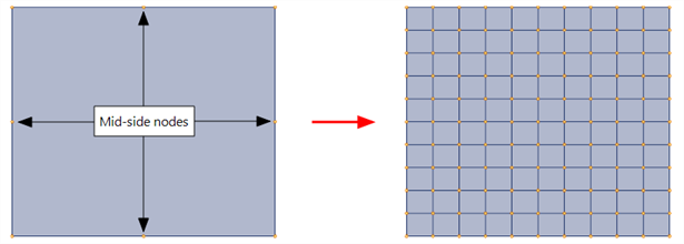
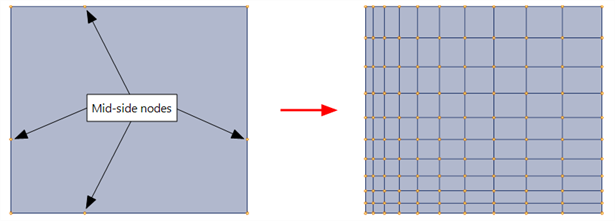
The position of the mid-side node on quadratic elements influences the resulting mesh. The reason for this is that elements are subdivided in parametric space, not in model space.
In the following figure, a single Quad8 with its mid-side nodes located at the geometric average of the corner nodes is subdivided into a mesh of 10 x 10 Quad4 elements. The resulting mesh is a uniform grid of elements with constant horizontal and constant vertical edge lengths.
In the following figure, the mid-side nodes are not in the middle, but shifted towards the bottom left corner of the element. The resulting mesh shows reducing element size towards the bottom left corner.
Common Uses
-
Subdivide can be used to globally refine a mesh for performing a convergence check.
-
Subdivide can be used to change the model to and from linear and quadratic versions of elements (e.g., convert a mesh consisting of Hexa20 and Wedge15 elements into the equivalent mesh of Hexa8 and Wedge6 elements by subdividing all elements with A=B=C=1 divisions and setting the appropriate target type).
-
The subdivide tool is also used extensively in conjunction with the grading tools when locally refining areas of the mesh.
See Also