Mesh Tools: Direct Solid Automesh
Description
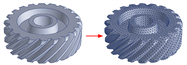
Automatically generates a solid mesh of tetrahedral brick elements from geometry face boundaries defining the surfaces of closed volumes.

This function consolidates the two-step process of Mesh Tools: Surface Automesh followed by Mesh Tools: Solid Automesh from Plates to generate brick elements directly from geometry faces. This approach can speed up the process of solid meshing, and it can also avoid problems that may occur with the two-step process when plate elements are inadvertently detached or zipped (particularly plate elements representing adjoining faces of separate solids).
The geometry faces must define a watertight (i.e., manifold) surface for each solid. Geometry faces containing free edges and/or T-junctions cannot be used for direct solid meshing.
The faces representing each solid must be in the same group, otherwise the solid cannot be identified.
Multiple solids can be meshed together even if they are in the same group. Internal cavities are automatically detected and will form voids in the meshed solid.
Dialog - Sizes Tab

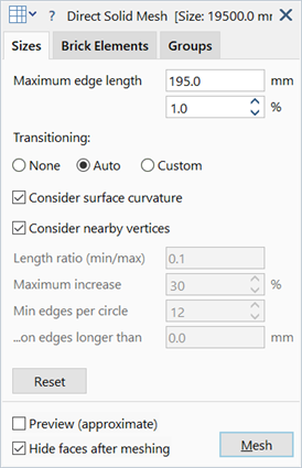
Maximum edge length
Maximum edge length of generated brick elements.
May be set as an absolute size in length units, or as a percentage of the nominal model size. Either parameter may be set, and the other will automatically change to match.
Transitioning
Additional controls used to constrain the surface element edge lengths.
-
None
Automesher will attempt to transition immediately to the maximum edge length from smaller elements, irrespective of small edges and other features. This usually leads to a more uniform mesh, but local detail at small features and edges with small radii may be skipped.
-
Auto
Automatically determines appropriate values for meshing controls, which are described below.
Edge lengths transition gradually from smaller elements towards the maximum edge length requested. Features and edges that are smaller than the maximum edge length will influence the local mesh size, and their effect will propagate a certain distance from the feature itself.
-
Custom
Provides for more detailed control of the meshing as described below.
Consider surface curvature
If set, the average surface curvature at the edges of the face is considered in addition to other edge constraints for the generation of plate elements. The curvature constraint is applied to the edges and to the face.
Consider nearby vertices
If set, vertices that are close to a face will influence the local mesh size on the face, even if those vertices are not part of the face. With this option, better transitioning of features across relatively thin solids can usually be obtained.
Length ratio (min/max)
Minimum edge length as a fraction of the maximum edge length.
Controls the minimum element size that may be generated in the mesh and overrides all other meshing controls except when an edge length is smaller than this ratio. At least one element will always be generated across an edge, irrespective of the edge length.
Maximum increase
Rate of increase or transitioning in edge length between adjacent elements.
For example a value of 10% means that an element edge length can be 10% bigger or smaller than its neighbour.
A value of 0% is allowed and enforces no transitioning.
Min edges per circle
Minimum number of elements to be placed around the circle or arc of a circle.
Applies to curves, arcs and any other edge with curvature. The number of actual divisions produced depends on the length of the arc in relation to the circumference of a circle with that same radius of curvature.
This condition will not be satisfied if the required edge length violates the Length ratio (min/max) setting.
...on edges longer than
Edges that are shorter than the value set here will not consider the Min edges per circle parameter.
Reset
Reverts meshing controls to default values.
Dialog - Brick Elements Tab

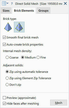
Brick type
Type of tetrahedral brick to generate. Can be either Tet4 or Tet10.
When Tet10 is selected, mid-side nodes on the surface elements will almost always be generated on the surface of the geometry faces. An exception to this is when the local surface curvature is concave and too small compared with the edge length of the element (e.g., a small fillet modelled with a curved surface element that is too large). In this situation, the mid-side node on the surface Tet10 might not lie on the surface of the geometry face, but might be moved off the surface slightly to avoid an invalid brick element.
The mid-side nodes of internal tetrahedra always remain at the linear mid position.
Smooth final brick mesh
If set, the generated brick mesh will be adjusted where possible to improve the internal angles on faces and the angles between faces of the tetrahedra.
Auto-create brick properties
If set, a new property set is automatically created whenever a generated brick mesh is assigned a new property number.
Internal mesh density
Desired internal element size.
-
Coarse
Attempts to transition to the maximum element size in the minimum number of steps.
Maximum element size is based on the largest edge length in the boundary mesh.
-
Medium
More gradual transition is used relative to the coarse mesh.
-
Fine
Minimal transitioning is used.
Adjacent solids
-
Zip using automatic tolerance
If set, adjacent solids are zipped using a zip tolerance based on the element edge lengths on the surface of the solid.
-
Zip using Element Zip Tolerance
If set, adjacent solids are zipped using the specified zip tolerance under Tool Options: Tolerance Tab.
-
Don't zip
If set, adjacent solids are not zipped.
Dialog - Groups Tab

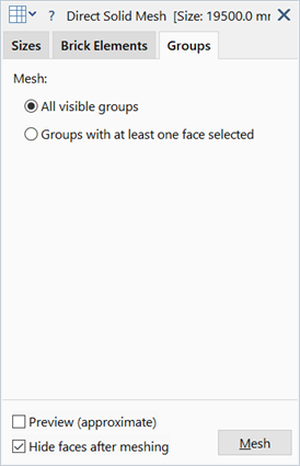
All visible groups
If set, all groups that are not hidden from view are included for solid automeshing.
Groups with at least one face selected
If set, only groups with at least one face selected are included for solid automeshing.
See Also